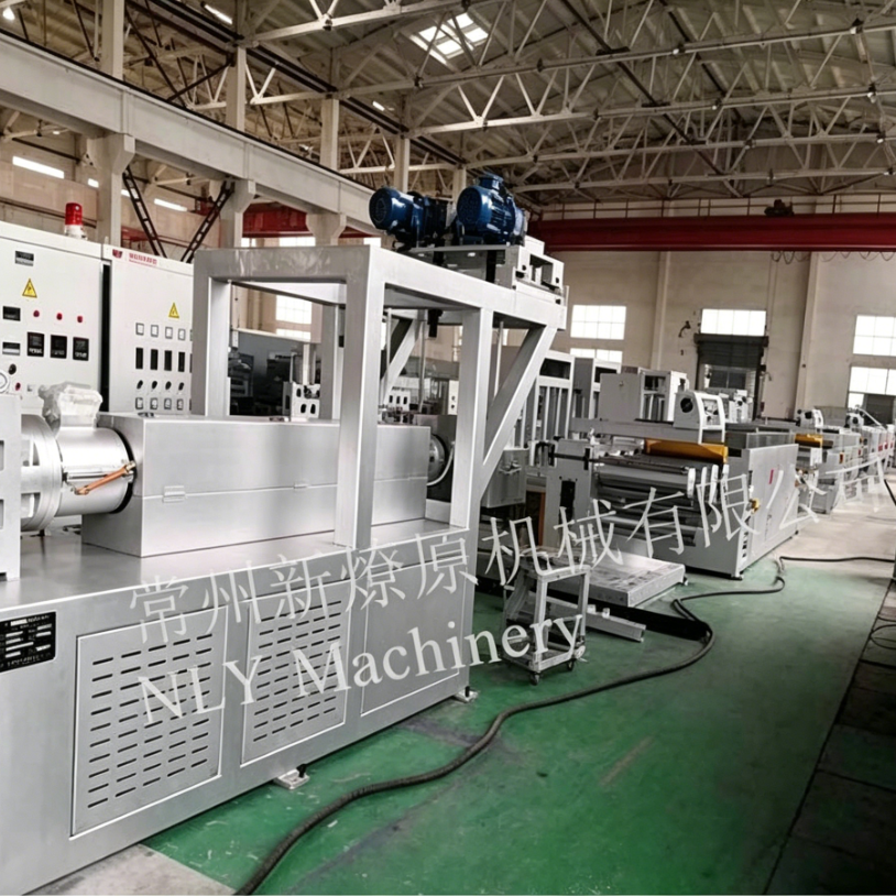
Industrial filtration monofilament is a critical component in woven filter mesh, filter cloth, screen media, and other precision filtration products. Unlike ordinary industrial monofilament, filtration yarn directly influences mesh opening, open area, pore-size distribution, permeability, and particle-retention performance.
For this reason, monofilament diameter tolerance cannot be specified by nominal diameter alone.
A complete filtration monofilament specification should define:
- Nominal diameter
- Diameter tolerance
- Ovality or out-of-roundness
- Measurement method
- Measurement axis
- Sampling frequency
- Acceptance criteria
- Statistical requirements such as CV%
- Production conditions under which the tolerance applies
The most important principle is simple:
A tighter diameter tolerance is not automatically a better filtration specification. The correct tolerance is the one that consistently produces the required mesh opening and filtration performance.
This article explains how to translate a filtration-media specification into a monofilament extrusion-line specification, how to measure diameter and ovality, what line components influence tolerance, and how to verify performance during a factory acceptance test (FAT).
What Is Filtration Monofilament?
Filtration monofilament is a single continuous polymer filament used to manufacture woven filtration media.
Common polymers include:
- PET (polyester)
- PA6 and PA66 (nylon)
- PP (polypropylene)
- PE and HDPE
- Other application-specific engineering polymers
The monofilament is typically woven into a mesh structure in which the filament diameter, mesh count, weave pattern, and finishing process determine the final filtration characteristics.
Typical applications include:
- Industrial filter cloth
- Filter mesh
- Screen printing mesh
- Chemical filtration
- Food and pharmaceutical filtration
- Water filtration
- Mining and mineral processing
- Industrial separation
- Technical woven fabrics
For filtration applications, filament diameter is therefore not simply a dimensional characteristic.
It is one of the variables that defines the final filtration geometry.
Why Monofilament Diameter Tolerance Matters in Filtration Mesh
In a woven mesh, the available opening between adjacent filaments depends on the relationship between:
Mesh pitch − filament diameter = approximate mesh opening
The actual geometry also depends on weave structure, filament shape, fabric construction, tension, and finishing.
This means that increasing filament diameter generally reduces the available opening, while decreasing filament diameter generally increases it.
A simplified example illustrates the relationship.
If the mesh pitch remains constant:
- Larger filament → smaller opening
- Smaller filament → larger opening
- Larger filament → lower open area
- Smaller filament → higher open area
Consequently, diameter variation along a production reel can contribute to variation in the finished mesh.
For precision filtration products, this can affect:
- Mesh opening
- Open area
- Pressure drop
- Permeability
- Particle retention
- Filtration rating
- Fabric thickness
- Weaving stability
The important conclusion is that filtration monofilament diameter should be controlled as a functional parameter, not simply as a cosmetic dimensional specification.
Diameter Alone Is Not Enough: Ovality Must Be Specified
One of the most important mistakes in filtration monofilament specifications is defining diameter without defining filament shape.
A filament can have an average diameter that is within tolerance while still being significantly oval.
For example, a filament may measure approximately:
0.80 mm × 0.76 mm
while its average or single-axis measurement may appear acceptable.
The resulting woven structure, however, may not behave like a truly round 0.80 mm filament.
This is why a filtration monofilament specification should normally contain two independent requirements:
1. Diameter tolerance
The allowable variation around the nominal diameter.
2. Ovality tolerance
The allowable difference between the maximum and minimum measured diameter.
A commonly used expression is:
Ovality = Maximum Diameter − Minimum Diameter
It may also be expressed as a percentage of nominal diameter.
What Causes Monofilament Ovality?
Diameter drift and ovality have different primary causes.
Diameter fluctuation
Longitudinal diameter variation is commonly associated with:
- Unstable polymer feeding
- Melt-pressure fluctuation
- Screw pulsation
- Melt-pump instability
- Temperature variation
- Material-viscosity variation
- Drawing instability
Ovality
Out-of-roundness is more commonly associated with:
- Asymmetric quenching
- Turbulent cooling
- Incorrect strand alignment
- Uneven water flow
- Uneven tension
- Poor strand positioning
- Mechanical misalignment
The distinction matters because the corrective action is different.
If diameter fluctuates, investigate melt delivery and drawing.
If ovality increases, investigate quenching and strand geometry.
Both problems can occur simultaneously.
How Should Filtration Monofilament Diameter Tolerance Be Specified?
A diameter specification should contain enough information that two independent laboratories would interpret it in the same way.
At minimum, define the following five elements.
Specification Element | What to Define | Why It Matters |
Nominal diameter | Target diameter and tolerance | Defines acceptable dimensional range |
Ovality | Maximum allowable out-of-roundness | Prevents flattened filament from passing on average diameter |
Measurement method | Contact or non-contact | Different methods can produce different readings |
Measurement basis | Single-axis, dual-axis, or 360° | Determines whether ovality can be detected |
Sampling plan | Samples, positions and frequency | Defines how production is evaluated |
Acceptance statistic | Average, maximum, percentile, CV%, etc. | Defines what constitutes a pass |
Without these elements, phrases such as “high precision,” “stable diameter,” or “tight tolerance” are difficult to verify objectively.
Diameter Tolerance vs. CV%: Why Both Can Be Useful
A tolerance band defines the permitted dimensional envelope.
For example:
Nominal diameter: 0.80 mm
Tolerance: ±0.005 mm
This means the specified range is approximately:
0.795–0.805 mm
However, this information does not tell you how the process is distributed inside that range.
Consider two production runs:
Run A
Most measurements:
0.799–0.801 mm
Run B
Measurements:
0.795–0.805 mm
Both may technically satisfy the same tolerance band, but Run A is much more tightly centered.
This is where coefficient of variation (CV%) can provide additional information.
CV% can help describe process consistency rather than simply whether measurements fall inside a pass/fail envelope.
For filtration yarn, a practical specification may therefore include both:
- Maximum diameter tolerance
- Target or maximum CV%
However, CV% should be agreed together with the measurement method and sampling plan. A CV calculated from a small number of measurements is not directly comparable with one calculated from continuous inline data.
What Diameter Tolerance Is Realistic for Filtration Monofilament?
There is no universal diameter tolerance for all filtration monofilaments.
The achievable tolerance depends on:
- Polymer type
- Filament diameter
- Polymer viscosity
- Resin consistency
- Production speed
- Extrusion output
- Spinneret geometry
- Melt filtration
- Melt metering
- Quenching
- Drawing ratio
- Godet synchronization
- Winding
- Measurement system
For this reason, a specification such as ±0.005 mm should be treated as a defined engineering target, not a universal industry standard.
A useful engineering framework is:
Application / Process Level | Example Engineering Target* |
General industrial monofilament | ±0.010 mm or application-specific |
Precision filtration yarn | ±0.005–0.008 mm |
High-precision filtration applications | ±0.003–0.005 mm |
Statistical process target | Defined CV% based on validated process |
*These are example engineering ranges, not universal guarantees. Actual achievable tolerance must be validated for the specified polymer, diameter, line speed, production output, and measurement method.
This distinction is particularly important when comparing extrusion-line suppliers.
A supplier should not simply state:
“Our machine can achieve ±0.005 mm.”
The correct question is:
Under what material, diameter, output, speed, measurement method, sampling plan, and process conditions is ±0.005 mm demonstrated?
Why Polymer Selection Changes Diameter Control
Different polymers behave differently during extrusion and drawing.
PET
PET is widely used for industrial filtration and technical woven fabrics because of its strength, dimensional stability, and processing characteristics.
However, PET is hygroscopic and normally requires appropriate drying before extrusion.
Moisture control is therefore an important part of diameter stability.
PA6 and PA66
Nylon monofilaments can provide good strength, flexibility, abrasion resistance, and fatigue performance.
PA is also moisture-sensitive, making drying and moisture management important.
PP
PP can be attractive because of its chemical resistance, low density, and cost advantages.
However, processing conditions can make diameter stability more challenging in some monofilament applications.
Therefore, the same tolerance target should not automatically be assumed for PET, PA, and PP.
Each polymer should have its own validated process window.
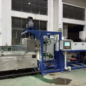
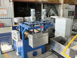
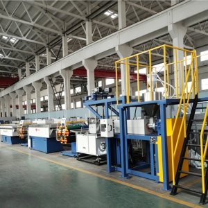
Which Extrusion Line Components Control Monofilament Diameter Tolerance?
A filtration monofilament extrusion line should be considered as an integrated process.
The typical process chain is:
Material Preparation → Drying → Extrusion → Melt Filtration → Melt Metering → Spinneret → Quenching → Drawing → Heat Setting → Winding → Diameter Measurement
Each section contributes differently to dimensional stability.
The following table summarizes the main relationships.
Tolerance Characteristic | Main Cause | Relevant Line Section | Recommended Specification |
Slow diameter drift | Filter loading, feeding, temperature drift | Extrusion / filtration | Pressure and temperature stability |
Short-term diameter oscillation | Screw pulsation, unstable melt flow | Melt metering | Positive-displacement melt pump |
Start-up sizing variation | Die swell and melt elasticity | Spinneret | Defined capillary geometry |
Die-related variation | Hole-size differences | Spinneret plate | Hole uniformity and precision |
Ovality | Uneven cooling | Quench system | Symmetric, stable quench flow |
Post-draw diameter variation | Draw instability | Drawing section | Synchronized godet drives |
Local thin spots | Godet slip | Godet system | Adequate traction and wrap |
Multi-end variation | Uneven thermal/hydraulic conditions | Quench + drawing | Path-to-path uniformity |
Winding-related instability | Tension fluctuation | Winder | Closed-loop tension control |
Undetected excursions | Insufficient measurement | Gauging system | Continuous inline measurement |
This leads to an important engineering principle:
The melt side primarily determines flow stability, the quench determines cross-sectional geometry, the drawing section determines final diameter and orientation, and the measurement system verifies whether the process remains within specification.
1. Melt Feeding and Extrusion Stability
1. 熔融进料与挤出稳定性
The first requirement for precision monofilament is stable polymer feeding.
Feed instability can cause changes in:
- Extruder loading
- Melt pressure
- Melt temperature
- Melt output
- Polymer residence time
- Final diameter
Common causes include hopper bridging, inconsistent regrind feeding, changes in material ratio, and poor raw-material consistency.
For recycled-material filtration yarn, controlling the recycled-to-virgin material ratio is particularly important.
The process recipe should define:
- Polymer grade
- Virgin/recycled ratio
- Drying conditions
- Feed rate
- Extruder speed
- Target output
2. Melt Filtration
Filtration protects the spinneret and helps maintain stable processing.
Contamination or excessive gel content can cause:
- Spinneret blockage
- Pressure increase
- Filament breaks
- Local diameter defects
- Uneven extrusion
As a filter becomes loaded, the pressure before the filter may gradually increase.
That creates a useful diagnostic signal.
If diameter slowly changes while filter pressure gradually rises:
Check filter loading before changing the draw ratio.
For precision filtration monofilament, the filtration system should therefore be specified according to:
- Polymer
- Contamination level
- Target diameter
- Production rate
- Required screen/filter fineness
- Screen-change method
- Acceptable pressure change
3. Melt Pump and Volumetric Metering
A positive-displacement gear pump can improve melt-flow stability between the extruder and spinneret.
Its primary function is to provide controlled volumetric melt delivery.
This can reduce the influence of:
- Screw pulsation
- Extruder output variation
- Pressure fluctuations
The important specification is not simply whether a line contains a gear pump.
Ask for:
- Pump capacity
- Speed-control resolution
- Inlet pressure control
- Outlet pressure range
- Volumetric stability
- Control-loop response
- Operating conditions used to demonstrate performance
A melt pump can significantly improve melt delivery, but it cannot compensate for unstable material, poor drying, excessive temperature variation, or an unstable downstream drawing process.
4. Spinneret and Die Geometry
The spinneret converts the melt into individual monofilaments.
For precision filtration yarn, important parameters include:
- Number of holes
- Hole diameter
- Hole uniformity
- Capillary length
- Capillary length-to-diameter ratio
- Die-land finish
- Spinneret material
- Manufacturing tolerance
Die swell also needs to be considered.
The polymer exits the capillary under pressure and may expand because of melt elasticity.
Therefore:
Spinneret hole diameter ≠ final filament diameter
The final diameter is established through the combined effects of:
Die geometry + melt conditions + cooling + drawing
This is why simply installing a smaller or larger spinneret hole does not automatically solve a diameter-tolerance problem.
5. Quench System: The Main Control for Ovality
The quench system determines how the freshly extruded filament solidifies.
For round filtration monofilament, cooling should be:
- Stable
- Symmetrical
- Repeatable
- Properly aligned
Important variables include:
- Water temperature
- Water level
- Flow rate
- Flow direction
- Turbulence
- Air gap
- Filament entry position
- Immersion length
A poorly designed or unstable quench can create cross-sectional asymmetry before the filament reaches the drawing section.
This is why quench design should be treated as a geometry-control system, not simply as a cooling tank.
6. Drawing and Godet Synchronization
Drawing determines the final filament diameter and molecular orientation.
The simplified relationship is:
Draw Ratio = Downstream Speed ÷ Upstream Speed
If downstream speed increases while extrusion output remains constant, the final filament generally becomes thinner.
If downstream speed decreases, the filament generally becomes thicker.
However, the actual result depends on material properties and the complete drawing schedule.
For precision filtration yarn, the important specification is therefore not merely the number of godet groups.
It is:
- Speed synchronization
- Draw-ratio repeatability
- Speed-control resolution
- Godet traction
- Filament tension
- Heating uniformity
- Draw-stage temperature
- Recipe repeatability
7. Preventing Godet Slip
Godet slip can create a particularly confusing diameter problem.
The motor may report exactly the programmed speed, while the filament experiences a different effective drawing speed because of insufficient traction.
Potential causes include:
- Contaminated surfaces
- Incorrect wrap
- Excessive wear
- Insufficient tension
- Incorrect contact geometry
- Polymer or oil buildup
The result can be:
Actual draw ratio ≠ programmed draw ratio
Therefore, when diameter suddenly changes without a corresponding motor-speed change, godet traction should be investigated.
8. Winding and Package Quality
Winding generally does not determine the original extrusion diameter.
However, winding affects:
- Package tension
- Package density
- Filament handling
- Unwinding behavior
- Creel performance
A filament that was dimensionally stable during extrusion can still create problems downstream if the package is poorly formed.
For filtration applications, the winding system should therefore provide consistent:
- Tension
- Traverse
- Package density
- Speed synchronization
How Should Filtration Monofilament Diameter Be Measured?
Measurement method is part of the specification.
A diameter value without a measurement method is incomplete.
Possible methods include:
- Micrometer
- Optical measurement
- Single-axis laser gauge
- Dual-axis laser gauge
- Multi-axis or 360° optical measurement
Each method has different capabilities.
Single-Axis vs. Dual-Axis Measurement
A single-axis measurement provides one dimensional reading.
It can detect diameter changes along the measured axis, but it cannot independently characterize out-of-roundness.
A dual-axis system measures two perpendicular dimensions.
For example:
X-axis = 0.801 mm
Y-axis = 0.796 mm
The difference provides information about ovality.
A 360° measurement system can provide a more complete cross-sectional assessment.
For filtration applications where filament geometry is critical, the measurement system should therefore be specified according to the required quality characteristic rather than simply by the word “laser gauge.”
Why Inline Diameter Measurement Matters
Periodic manual sampling can confirm product quality after production, but it cannot continuously observe what happened between two samples.
An inline laser gauge can monitor the filament continuously and provide:
- Real-time diameter
- Diameter trend
- Alarm detection
- Process drift identification
- Statistical data
- Closed-loop control where configured
This changes the production strategy from:
Make → Sample → Discover Problem
to:
Measure → Detect → Correct → Verify
That difference can significantly reduce the amount of material produced during an unstable period.
Inline Measurement vs. Offline Inspection
Feature | Inline Measurement | Offline Measurement |
Continuous monitoring | Yes | No |
Real-time alarm | Yes | No |
Process feedback | Yes | No |
Final QC verification | Limited | Yes |
Detailed laboratory analysis | Limited | Yes |
Ovality analysis | Depends on gauge | Yes, with suitable instrument |
Trend analysis | Excellent | Limited |
Dispute resolution | Useful | Important |
The most robust quality system uses both.
Inline measurement controls the process. Offline measurement independently verifies the finished product.
How to Design a Sampling Plan
A filtration monofilament specification should define the sampling plan before production begins.
A practical plan may include:
Lot definition
Define whether a lot means:
- One continuous production run
- One defined reel length
- One production batch
- Another mutually agreed unit
Avoid defining the lot simply as “one shipment” if the shipment contains material produced under different conditions.
Sampling position
Samples can be taken from:
- Beginning of reel
- Middle of reel
- End of reel
- Defined intervals throughout the production run
Replicate measurement
Take multiple measurements from different sections rather than measuring the same point repeatedly.
Report
Record:
- Average
- Maximum
- Minimum
- Range
- Standard deviation
- CV%, where required
- Ovality
- Measurement conditions
This creates a much stronger quality record than simply reporting:
“Diameter: PASS.”
Factory Acceptance Testing for Filtration Monofilament Lines
A factory acceptance test should prove more than whether the machine can start.
For a precision filtration monofilament line, the FAT should demonstrate that the line can maintain the agreed process conditions and product specification for a defined period.
1. Define the material
Record:
- Polymer grade
- Resin supplier
- Virgin/recycled ratio
- Moisture condition
- Drying parameters
2. Define the production recipe
Record:
- Extruder temperature
- Die temperature
- Melt pressure
- Melt-pump speed
- Extruder speed
- Quench temperature
- Godet speeds
- Draw ratio
- Heating conditions
- Winding speed
- Target diameter
3. Verify measurement equipment
The FAT should define:
- Gauge type
- Calibration status
- Measurement axes
- Calibration traceability
- Measurement frequency
4. Run continuously
A meaningful FAT should include an agreed continuous production period rather than only a short demonstration.
5. Record diameter trends
The complete diameter trend should be retained.
This allows the buyer to see:
- Start-up behavior
- Stabilization time
- Short-term variation
- Long-term drift
- Any excursions
6. Perform independent offline measurements
Samples from the production run should be checked independently.
This verifies that the inline system and laboratory measurement are consistent.
What Should Be Included in a Filtration Monofilament Line Specification?
A strong purchase specification can include the following categories.
Product specification
- Polymer
- Nominal diameter
- Diameter tolerance
- Ovality tolerance
- Required CV%
- Final application
- Required production output
Extrusion system
- Extruder type
- Screw design
- Feeding system
- Temperature-control zones
- Melt-pressure measurement
- Melt filtration
- Screen-changing system
- Melt pump
Spinneret
- Hole number
- Hole diameter
- Capillary geometry
- Hole uniformity
- Die material
- Die replacement procedure
Quench
- Water temperature range
- Temperature uniformity
- Flow configuration
- Air gap
- Immersion length
- Strand alignment
Drawing
- Number of stages
- Godet speed synchronization
- Draw-ratio range
- Draw-ratio resolution
- Heating method
- Temperature control
- Tension control
Winding
- Winding speed
- Tension range
- Traverse system
- Package size
- Package density
Measurement
- Inline diameter gauge
- Measurement axes
- Calibration
- Alarm limits
- Data logging
- Closed-loop control
- Offline verification
Which Configuration Choices Matter Most?
Not every item on an extrusion-line quotation has the same influence on diameter tolerance.
Configuration | Influence on Diameter Control | Priority |
Stable polymer feeding | High | Essential |
Melt-pressure monitoring | High | Essential |
Positive-displacement melt pump | High | Strongly recommended for precision lines |
Stable melt filtration | High | Essential |
Precision spinneret | High | Essential |
Symmetric quench | High for ovality | Essential |
Synchronized godets | High | Essential |
Stable drawing temperature | High | Essential |
Closed-loop winding tension | Moderate | Recommended |
Inline laser measurement | High for detection/control | Strongly recommended |
SPC data logging | Moderate to high | Recommended |
Higher extruder nameplate speed | Limited direct effect | Application dependent |
Longer machine footprint | Application dependent | Not inherently a tolerance feature |
This helps buyers avoid a common mistake:
comparing machines by component count instead of process capability.
A longer machine is not automatically more precise.
A larger extruder is not automatically more stable.
More drawing stages are not automatically better.
More sensors are not automatically better.
The correct question is:
Which component controls which source of variation, and how will that performance be demonstrated?
Questions to Ask a Monofilament Extrusion Line Supplier
Production
- What continuous production length can the line achieve at the target diameter?
- How quickly does the line stabilize after startup?
- How are diameter excursions detected?
- What operator response is required?
- Which production parameters can be locked?
Engineering
- What melt pump configuration is used?
- How is melt-pressure stability controlled?
- What is the spinneret capillary geometry?
- How is hole uniformity controlled?
- How is quench flow stabilized?
- How are godet speeds synchronized?
- What is the available draw-ratio resolution?
Quality
- What measurement method is used?
- Is the system single-axis, dual-axis, or 360°?
- How is ovality calculated?
- What calibration standard is used?
- What is the sampling plan?
- Is continuous diameter data available?
- Can raw production data be exported?
Procurement
- Which tolerance values are contractually guaranteed?
- Under what material and production conditions?
- What happens if the FAT result does not meet the agreed tolerance?
- What spare parts are included?
- What are the expected service intervals?
Management
- What is the expected production output?
- What is the expected scrap rate?
- What is the specific energy consumption?
- What commissioning support is included?
- What is the expected return on investment for the selected tolerance?
Common Red Flags When Comparing Extrusion Lines
Be cautious if a supplier provides a tolerance number without specifying the conditions.
Red flag 1: “±0.005 mm guaranteed”
Ask:
At what diameter?
For which polymer?
At what output?
At what line speed?
Measured how?
Red flag 2: Diameter tolerance without ovality
A filament can pass average diameter inspection while remaining out of round.
For filtration mesh, this can be a significant specification gap.
Red flag 3: Single-axis measurement presented as complete geometry control
A single-axis gauge cannot fully characterize filament ovality.
Red flag 4: Spot checks only
If the supplier demonstrates ten measurements and all ten pass, ask what happened during the rest of the production run.
Continuous trend data is much more informative.
Red flag 5: No defined FAT acceptance criteria
If nobody has agreed on:
- Material
- Diameter
- Tolerance
- Sampling
- Measurement
- Duration
- Pass/fail rule
then the FAT is not a meaningful acceptance test.
Recommended Contract Clauses for Filtration Monofilament Lines
The following clauses can be adapted for a purchase specification:
Diameter Measurement: Monofilament diameter shall be continuously monitored using a calibrated non-contact measurement system during the agreed factory acceptance test.
Ovality: Monofilament ovality shall be measured separately using a dual-axis or suitable multi-axis measurement method. The maximum allowable ovality shall be defined in the technical specification.
Measurement Traceability: Measurement equipment used for acceptance testing shall have valid calibration and traceability documentation available before the test.
Sampling: Final acceptance shall include an agreed sampling plan defining production lot, sample positions, number of specimens, replicate measurements, and acceptance statistics.
FAT Acceptance: The extrusion line shall demonstrate stable production within the agreed diameter and ovality specifications for the defined FAT duration and production conditions.
Data Records: The supplier shall provide agreed production records, diameter trends, measurement results, calibration documentation, and FAT records.
These clauses should be reviewed and adapted by the buyer’s engineering, quality, and procurement teams before being incorporated into a binding contract.
The Most Effective Troubleshooting Sequence
When diameter variation appears during filtration monofilament production, do not change multiple parameters at the same time.
Use this sequence:
Step 1 — Check melt pressure
Look for:
- Periodic oscillation
- Gradual pressure increase
- Sudden pressure changes
Step 2 — Check melt temperature
Compare actual temperature trends with the process recipe.
Step 3 — Check material
Verify:
- Resin batch
- Moisture
- Recycled ratio
- Feeding stability
Step 4 — Check filtration
Look for increasing pressure drop or screen loading.
Step 5 — Check quenching
If ovality is present, prioritize:
- Water temperature
- Flow
- Turbulence
- Strand alignment
Step 6 — Check drawing
Verify:
- Godet speeds
- Draw ratio
- Tension
- Traction
- Heating
Step 7 — Check winding
Only after upstream stability is confirmed should winding tension and package formation become the primary focus.
This sequence reduces unnecessary process adjustments and makes the root cause easier to identify.
Diameter Tolerance Is a System Specification
The most important conclusion for a filtration-media producer is that monofilament diameter tolerance is not created by one machine component.
A stable result requires the complete process to work together:
Stable material → stable feeding → stable extrusion → stable melt filtration → stable metering → consistent spinneret geometry → uniform quenching → synchronized drawing → controlled winding → continuous measurement
Each stage removes or controls a different source of variation.
The measurement system then confirms whether the final result meets the specification.
This leads to a simple engineering rule:
Remove variation upstream before attempting to correct it downstream.
A laser gauge can detect diameter variation.
A closed-loop system can correct suitable slow changes.
But neither can compensate indefinitely for an unstable melt, poor quenching, or uncontrolled drawing process.
Frequently Asked Questions
What diameter tolerance should a filtration monofilament line achieve?
There is no single tolerance suitable for every filtration monofilament.
Precision applications may target approximately ±0.003–0.005 mm, while other filtration applications may use wider bands such as ±0.005–0.010 mm or more.
The correct target depends on polymer, diameter, mesh specification, production speed, measurement method, and required filtration performance.
What is the difference between diameter tolerance and ovality?
Diameter tolerance controls the size of the filament.
Ovality controls how round the filament is.
Both should be specified separately when filament geometry is important.
Can a single-axis laser gauge measure ovality?
No.
A single-axis measurement provides one dimensional reading. To calculate out-of-roundness, the system needs measurements in at least two directions or an appropriate multi-axis/360° measurement method.
Is ±0.005 mm a universal standard for filtration monofilament?
No.
±0.005 mm should be treated as an engineering target for a defined application and process, not as a universal industry standard.
The target should be validated under actual production conditions.
Does a melt pump improve monofilament diameter stability?
It can.
A positive-displacement melt pump can stabilize volumetric melt delivery and reduce the influence of screw and pressure fluctuations.
It does not eliminate problems caused by wet resin, unstable temperatures, poor cooling, incorrect drawing, or mechanical slip.
Why does monofilament diameter increase during a long production run?
Possible causes include:
- Screen/filter loading
- Increasing melt pressure
- Temperature drift
- Feeding instability
- Material-property changes
Compare the diameter trend with melt-pressure and temperature trends to identify the relationship.
Why is PP sometimes more difficult to control than PET or PA?
Polymer rheology and processing behavior differ between materials.
PP monofilament can require particularly careful control of extrusion, spinning, cooling, and drawing conditions.
Therefore, a tolerance demonstrated for PET or PA should not automatically be assumed for PP.
Is a tighter tolerance always better?
No.
A tolerance tighter than the actual filtration-media requirement can increase:
- Equipment cost
- Process complexity
- Scrap risk
- Setup sensitivity
The correct goal is repeatable tolerance that supports the required mesh opening and filtration performance.
What should be included in a filtration monofilament extrusion-line specification?
At minimum:
- Polymer type
- Target diameter
- Diameter tolerance
- Ovality tolerance
- CV% target where appropriate
- Measurement method
- Sampling plan
- Melt filtration
- Melt metering
- Spinneret specification
- Quench specification
- Drawing configuration
- Godet synchronization
- Winding control
- Inline measurement
- FAT procedure
Final Takeaway
For industrial filtration monofilament, the question is not simply:
“How tight is the diameter tolerance?”
The better question is:
“Can the extrusion line repeatedly produce the diameter, ovality, and statistical consistency required by the final filtration specification?”
A reliable filtration monofilament process combines:
Stable melt delivery + controlled filtration + precise spinneret geometry + uniform quenching + synchronized drawing + controlled winding + continuous measurement.
Before purchasing an extrusion line, define the product specification first.
Then define:
Diameter → Ovality → Measurement → Sampling → Acceptance → Line Configuration → FAT
This approach prevents equipment specifications from becoming disconnected from the actual filtration application.
For producers developing PET, PA, PP, PE, PBT, or recycled-material filtration monofilament, NLY can evaluate the target filament diameter, material, output, draw ratio, cooling requirements, and tolerance target and translate those requirements into a complete monofilament extrusion-line configuration.
The objective should not simply be the smallest tolerance number on a quotation.
The objective is stable, repeatable production that consistently delivers the filtration performance your customer has specified.