.jpg)
If you’ve ever chased diameter variation, periodic surging, or unexplained scrap on a monofilament line, the root cause often starts before the filament even hits the die.
The extruder’s job in monofilament production is simple to state and hard to execute: deliver a clean, uniform melt at a stable pressure and temperature to the die.
This article explains the plastic monofilament extruder working principle, focusing only on the extruder section (not quench, drawing, annealing, or winding).
Plastic monofilament extruder working principle in one sentence
A plastic monofilament extruder takes solid polymer (pellets/granules), conveys it forward, melts it, homogenizes it, builds pressure, filters it, and meters it so the die sees a stable melt stream.
That stability is what keeps downstream stages predictable.
The main parts of a monofilament extruder (and why each exists)
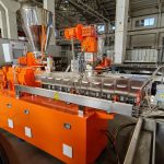
A typical monofilament line uses a single-screw extruder. The exact configuration varies by polymer (PP/PE/PET/PA) and target filament size, but the extruder section usually includes:
Hopper + feed throat: gets resin into the screw and starts solids conveying.
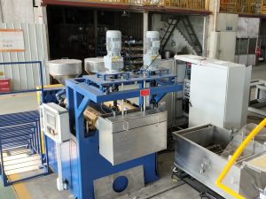
Screw + barrel: the core “engine” that conveys, melts, and pressurizes.
Barrel heating zones (and cooling): holds a controlled temperature profile.
Drive motor + gearbox: provides torque and stable screw speed.
Breaker plate + screen pack / screen changer: filtration and flow stabilization.
(Optional) melt pump (gear pump): decouples output from screw pressure fluctuations.
Pressure and temperature sensors: tells you if the process is actually stable, not just “set stable.”
Single screw extruder working principle: what happens inside the barrel
A single-screw extruder is usually described in three functional zones: feed, compression/transition, and metering.
1) Feed zone: solids conveying starts here
In the feed zone, polymer is still mostly solid.
The screw channel is deeper to accept material.
The screw drags pellets forward as they rub against the barrel wall.
Why it matters for monofilament: if feeding is inconsistent (bridging, rat-holing, surging feeders), the screw won’t build a steady solid bed. That turns into pulsating output later.
Pro Tip: If head pressure is cycling and your diameter is “breathing,” don’t start at the die. Watch feeder behavior and motor load first.
2) Compression (transition) zone: melting and pressure build-up
As material moves forward, the screw channel depth reduces. This compacts the solid bed, raises pressure, and accelerates melting.
Melting is not just “the heaters melt the plastic.” In practice, a big portion of melting comes from viscous dissipation (shear heating) in the thin melt film between the solid bed and the barrel wall. Plastics Technology’s Mark Spalding walks through this melting mechanism in “Understanding Screw Temperature in Single-Screw Extruders” (Plastics Technology).
Why it matters for monofilament: incomplete melting, unstable melt temperature, or an unstable solid bed can show up as:
periodic pressure oscillation,
gels/unmelted fragments,
inconsistent draw behavior downstream.
3) Metering zone: stabilize the melt before filtration and the die
By the metering zone, the goal is that the polymer is fully molten and more uniform.
The channel depth is relatively constant.
The screw acts like a pump to deliver a steadier flow.
Why it matters for monofilament: this is where you win or lose melt stability. If the melt temperature drifts, viscosity changes. If viscosity changes, output and die pressure change.
Filtration: screen pack and screen changer in extrusion
After the screw, the melt commonly passes through a breaker plate + screen pack (or a continuous screen changer / melt filter).
Filtration has two jobs:
Catch contamination (gels, black specks, unmelted particles).
Add flow resistance (backpressure) that can improve mixing and stabilize flow.
But there’s a tradeoff: as screens load up, pressure rises. That can destabilize output if the system can’t compensate.
Pressure control: what you should measure (and how to interpret it)
For monofilament, pressure stability at the die feed is closely tied to diameter stability.
Two practical points from Plastics Technology:
Where you measure matters, and discharge pressure is the most critical measurement for both safety and process understanding.
Some pressure “noise” is normal because screw rotation creates cyclical pressure features; sampling and interpretation matter.
A good technical reference is “Pressure Measurement Basics for Single-Screw Extruders” (Plastics Technology).
What to watch on the panel (extruder section)
Head/adaptor pressure trend: rising trend often indicates screen loading or restriction.
Pressure oscillation: may indicate feed instability, temperature control cycling, or screw speed fluctuations.
Motor load (amps/torque): spikes can indicate viscosity increase, restriction, or feeding issues.
Melt temperature stability: not just setpoint, but actual stability (and uniformity across zones).
Melt pump in extrusion: why many monofilament lines use one
A melt pump (gear pump) sits after the extruder and before the die.
Its purpose is straightforward: deliver a more constant volumetric flow to the die and reduce the effect of pressure fluctuations from the screw.
This doesn’t “fix” bad melting or moisture, but it can dramatically improve stability when the melt quality is good and the goal is tight diameter control.
Extruder surging causes (common ones that show up as diameter variation)
When operators say “the line is unstable,” the extruder-side causes usually fall into a few buckets:
What you see | Likely extruder-side cause | First checks |
|---|---|---|
Head pressure slowly rises, output slowly falls | Screen pack loading / restriction | Screen differential pressure, screen change interval, contamination level |
Head pressure oscillates at a repeatable rhythm | Feed inconsistency or temperature cycling | Hopper bridging, feeder speed stability, heater/PID cycling |
Diameter varies but temperatures look “fine” | Melt temperature isn’t uniform or sensors are misleading | Verify thermocouples, check actual melt temp near adaptor if possible |
Bubbles/voids, sputtering, unstable flow | Moisture or volatiles in resin | Dryer performance, resin handling, dew point, material lot change |
For a broader troubleshooting lens on temperature’s effect on extrusion quality, Plastics Technology’s coverage on melt temperature control is a useful starting point (see the PT Online article cited above on screw temperature and melting behavior).
Where NLY fits (without turning this into a sales pitch)
If your goal is stable monofilament output, the extruder configuration has to match:
resin type,
target diameter range,
output rate,
filtration needs (virgin vs. recycled feed),
and your acceptable pressure/temperature control scheme.
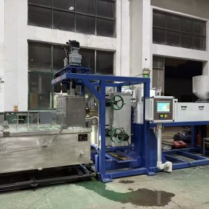
NLY (Changzhou New Liaoyuan Machinery Co., Ltd.) publishes example configurations that show concrete extruder parameters like screw L/D and pressure feedback control, such as the 125kgh PE monofilament rope making machine (80mm screw, L/D 33:1) and the 100kgh monofilament extrusion machine (85mm screw, L/D 30:1).
Next steps
If you want, share these three inputs and we can map them to an extruder-side control plan:
polymer (PP/PE/PET/PA) and whether it’s virgin or recycled,
target filament diameter range,
target output (kg/h).
From there, you can have NLY propose an extruder configuration (screw L/D, filtration approach, and pressure feedback or melt-pump options) that fits your stability goals.