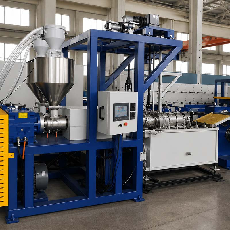
In continuous plastics manufacturing, electricity is usually the second highest operating expense after raw resin. For plant managers operating 24/7 extrusion lines—whether producing monofilament yarns, sheet, pipe, or technical profiles—electricity bills are directly tied to overall operating margins.
However, simply telling operators to “use less power” rarely yields permanent savings. Cutting barrel setpoints too drastically causes unmelted resin gels, pressure spikes, and catastrophic die clogs. Lowering screw speeds without adjusting line synchronization reduces hourly output, which actually increases the energy required to process each kilogram of plastic.
To permanently reduce electricity costs, process engineers must focus on Specific Energy Consumption (SEC) rather than gross daily power draw. SEC measures the total electrical energy required to produce a single kilogram of acceptable, within-spec product. By shifting the objective from lowering total electricity use to minimizing kWh per kilogram, manufacturing plants can unlock 15% to 35% in energy savings while maintaining strict dimensional tolerances and melt stability.
This guide details the core energy breakdown of extrusion lines, establishes technical SEC benchmarks for key polymers, and outlines five high-impact steps to systematically lower energy consumption on the factory floor.
Understanding Extrusion Energy Distribution (The 50/30/15/5 Rule)
Before launching an energy audit, process engineers need to understand where electrical power actually goes during operation. In a standard continuous plastic extrusion system, energy input is distributed across four primary subsystems:
Main Extruder Drive Motor (33% – 65%, average ~50%): The largest single power consumer on the line. The drive motor powers screw rotation, solids conveying, resin compaction, and mechanical shear melting.
Barrel & Die Heating Systems (8% – 40%, average ~30%): Conductive electrical resistance heaters that bring the barrel zones up to processing temperature and maintain thermal stability across the melt stream.
Cooling & Utility Systems (10% – 30%, average ~15%): Barrel cooling blowers, quench water circulation pumps, chillers, and vacuum calibration units.
Auxiliary Equipment (5% – 10%): Resin feeding, desiccant hoppers, melt gear pumps, haul-off godets, winders, and material conveyance.
As documented in the APenergy 2024 extrusion energy analysis, electricity consumption in plastic processing is roughly split 50/50 between the drive motor (mechanical work) and thermal/auxiliary systems.
Calculating Specific Energy Consumption (SEC)
To establish an accurate energy baseline, plant managers must measure line performance using the Specific Energy Consumption formula:
SEC (kWh/kg) = Total Line Electricity Input (kWh)/Good Production Output Mass (kg)
Measuring SEC requires sub-metering the extruder and its primary utilities (or logging main PLC energy meters) over a defined production shift, then dividing by the net weight of spec-compliant product packaged.
Pro Tip: Always calculate SEC using good saleable output rather than gross throughput. Unusable scrap generated during startup, changeovers, or diameter drift consumes electrical energy without producing marketable tonnage, artificially inflating your real energy costs.
Baseline SEC Benchmarks by Polymer
The theoretical energy needed to raise a polymer from room temperature to its melt processing temperature varies based on polymer enthalpy, crystallinity, and drying requirements.
Polymer Type | Theoretical Thermal Energy to Melt | Typical Extruder Process Load | Target Full-Line SEC Benchmark | Key Energy Driver |
|---|---|---|---|---|
Polypropylene (PP) | ~0.16 kWh/kg | 0.20 – 0.32 kWh/kg | 0.35 – 0.50 kWh/kg | Moderate melt temp (210–250°C); fast crystallization; no pre-drying required. |
High-Density Polyethylene (HDPE) | ~0.16 kWh/kg | 0.22 – 0.34 kWh/kg | 0.35 – 0.50 kWh/kg | High shear sensitivity; lower thermal processing requirements. |
Polyester (PET) | ~0.10 kWh/kg | 0.25 – 0.38 kWh/kg | 0.45 – 0.65 kWh/kg | Requires high-temp desiccant pre-drying (160–170°C, -40°C dew point) and high melt temps. |
Polyamide / Nylon (PA6 / PA66) | ~0.18 kWh/kg | 0.28 – 0.42 kWh/kg | 0.50 – 0.70 kWh/kg | High melt processing temps (240–295°C) and hygroscopic dehumidification. |
If your plant operates above these benchmark ranges, your lines are losing significant energy through thermal radiation, inefficient motor drives, poor screw shear efficiency, or process instability.
Step 1: Mitigate Thermal Losses with Barrel Insulation & Smart Heating
Uninsulated extruder barrels act as giant space heaters, radiating substantial thermal energy into the surrounding factory air. Uninsulated ceramic resistance heater bands operate at external surface temperatures between 250°C and 350°C, wasting up to 30% to 40% of their electrical input directly into the ambient environment. This waste is compounded during summer months, as plant HVAC and chiller systems must consume extra electricity to cool the building.
Installing Custom Barrel Thermal Jackets
Installing removable ceramic fiber or multi-layer insulation jackets over the extruder barrel zones is one of the fastest, highest-ROI capital retrofits available to extrusion plants.
Thermal Radiation Loss: Reduced by 70% to 85%.
Electrical Heater Duty Cycle: Reduced by 15% to 30%.
Payback Period: Typically 3 to 8 months depending on local kWh tariffs.
Beyond direct kWh savings, barrel insulation eliminates localized draft cooling caused by overhead plant fans or open loading doors, providing tighter zone temperature control (within ±1°C) and improving melt consistency.
Uninsulated Barrel (30-40% Radiation Loss) ➔ Add Ceramic Insulation Jackets ➔ 70-85% Less Heat Loss ➔ Lower Heater Duty & Stable Melt
Upgrading to Electromagnetic Induction or Ceramic IR Heating
When replacing worn heater bands, consider upgrading from traditional mica or ceramic resistance bands to electromagnetic induction heating or ceramic infrared (IR) heaters.
According to a Plastics Engineering (SPE) report on polymer extrusion efficiency, induction heating systems generate thermal energy directly inside the steel barrel wall via alternating magnetic fields, rather than transferring heat conductively through external contact. This raises heating thermal efficiency from ~60% to over 90%, shortening cold-start preheating times by up to 50%.
Eliminating Heating vs. Cooling “Temperature Fighting”
A common hidden waste on extrusion barrels equipped with forced-air cooling blowers is control loop oscillation. If PID temperature parameters are poorly tuned, the heating bands may energize while the zone cooling blowers are simultaneously running to bleed off excess heat.
Audit your PLC temperature controllers to ensure a clean deadband zone (typically 1.5°C to 3.0°C) between the heating trigger point and the cooling fan activation point.
Step 2: Modernize Drive Systems (VFDs, PMSM, & Direct Drive)
Because the main drive motor accounts for roughly half of the total electrical bill, drive system efficiency is critical to achieving a low SEC.
Replacing Fixed-Speed AC Motors with Variable Frequency Drives (VFDs)
Older extruders operating with traditional AC induction motors running directly across the line (or choked via eddy-current couplings and mechanical speed variators) waste huge amounts of electrical energy as heat under partial load conditions.
Retrofitting main motors and auxiliary pumps with Variable Frequency Drives (VFDs) allows the motor to draw only the exact amperage required for the actual torque and RPM demand. In auxiliary water pumps and air blowers, reducing motor speed by just 20% using a VFD reduces electrical power draw by nearly 45% due to affinity laws.
Upgrading to Permanent Magnet Synchronous Motors (PMSM)
When replacing or refurbishing main extruder drives, upgrading from standard IE2/IE3 AC induction motors to IE4 or IE5 Permanent Magnet Synchronous Motors (PMSM) offers substantial energy savings:
Full-Load Efficiency: PMSM motors achieve 96% to 97.5% efficiency compared to 91%–93% for standard induction motors.
Partial-Load Performance: PMSM motors maintain near-peak efficiency across a wide speed torque curve (from 20% to 100% rated RPM), whereas standard induction motors suffer steep efficiency drops when throttled down.
Eliminating Gearbox Losses with Direct-Drive Technology
Traditional extruders transmit motor torque to the screw through a multi-stage mechanical gearbox and belt drive. Mechanical friction, oil churning, and belt slippage consume 10% to 15% of the motor’s shaft horsepower before it ever reaches the screw.
Modern high-efficiency extruders utilize direct-drive torque motors mounted directly onto the thrust bearing assembly. By removing the gearbox entirely, direct-drive systems eliminate mechanical transmission losses, operate virtually silently, and reduce drive-train maintenance.
When evaluating plant modernizations, plant managers should review how machinery design impacts total cost of ownership; understanding monofilament extrusion machine cost factors helps quantify the long-term ROI of high-efficiency drive options.
Step 3: Optimize Screw Geometry to Balance Shear vs. Conductive Heat
In a well-designed single-screw extruder, electrical barrel heaters should not supply the majority of the energy required to melt the plastic resin during steady-state production. Instead, 70% to 80% of the thermal energy needed for plasticization should be generated mechanically through viscous shear dissipation—the mechanical friction created as the rotating screw shears the polymer melt against the barrel wall.
Electrical Heating (Startup & Thermal Control ~20-30%) + Mechanical Shear Work (Rotational Screw Energy ~70-80%) ➔ Homogeneous Polymer Melt
Mechanical energy conversion via screw shear is inherently more energy-efficient than electrical resistance heating because energy is delivered directly into the core of the polymer matrix rather than relying on thermal conduction through low-conductivity plastic solids.
Selecting the Right Screw Profile
If an extruder relies heavily on electrical heater bands remaining on 100% duty cycle during production, the screw geometry is likely inefficient for that polymer.
Low Compression Ratio / Shallow Flights: Causes insufficient shear heat generation, forcing electrical barrel heaters to do the heavy lifting and driving up SEC.
Excessive Shear / Aggressive Barrier Flights: Generates excessive friction, overheating the polymer melt. This forces automatic barrel cooling blowers to turn on, effectively blowing expensive electrical energy out into the room as hot air.
Optimized Barrier & Mixing Screws: A properly configured barrier screw separates the solid bed from the liquid melt pool, maintaining uniform shear rates, lowering melt temperatures by 10°C to 15°C, and reducing overall kWh consumption per kilogram.
When upgrading existing equipment or specifying a new production line, learning how to choose the right plastic monofilament extrusion machine ensures that screw L/D ratio, flight depth, and drive power are perfectly matched to your specific polymer rheology.
Step 4: Maximize Throughput & Line Synchronization
One of the most effective operational methods to reduce extrusion energy consumption per kilogram is running the line closer to its rated continuous capacity.
The Mathematics of Base Idle Load Dilution
Every extrusion line has a fixed “base idle load”—the baseline electrical power required to keep barrel zones at temperature, power the PLC panels, run quench pumps, and spin auxiliary rollers, regardless of whether the line is extruding 20 kg/h or 100 kg/h.
Consider an extrusion line with a fixed auxiliary/thermal base load of 15 kW and a main drive that draws 0.20 kWh/kg:
Operating at 50 kg/h: Base load contributes 15 kW / 50 kg/h = 0.30 kWh/kg. Total SEC = 0.20 + 0.30 = 0.50 kWh/kg.
Operating at 100 kg/h: Base load contributes 15 kW / 100 kg/h = 0.15 kWh/kg. Total SEC = 0.20 + 0.15 = 0.35 kWh/kg.
By doubling line output toward its designed continuous limit, the plant achieves a 30% reduction in Specific Energy Consumption without changing a single piece of hardware.
⚠️ Warning: Never increase screw speed beyond the line’s thermal or downstream cooling limit. Over-speeding an extruder can cause melt pressure fluctuations and diameter variation. Plant operators should learn how to increase monofilament extrusion line output without losing stability to ensure quality standards are preserved.
Synchronizing Downstream Cooling and Drawing Systems
In multi-stage continuous processing lines—such as monofilament drawing lines—downstream thermal systems (hot water quench baths, steam ovens, heated godets) represent major energy consumers.
Quench Water Management: Keep quench bath temperatures tightly regulated. Excessively cold water requires higher chiller compressor power and forces downstream drawing ovens to work harder to reheat the filament.
Air Knife & Dewatering Efficiency: Use high-efficiency slot air knives powered by centrifugal blowers rather than compressed air nozzles for strand dewatering. Compressed air is one of the most expensive energy vectors in a manufacturing plant.
Diameter Stability & Scrap Reduction: Inconsistent strand tension or temperature variation leads to frequent strand breaks and startup scrap. Following best practices to achieve stable filament diameter prevents line restarts and maintains continuous production at peak SEC efficiency.
Step 5: Implement a Plant Energy Audit & Maintenance Checklist
To maintain low Specific Energy Consumption over time, plant managers should establish a routine preventive maintenance and energy monitoring schedule.
Audit Item | Inspection Frequency | Action Required | Expected Energy Benefit |
|---|---|---|---|
Barrel Insulation Inspection | Monthly | Inspect insulation jackets for tears, gaps, or oil saturation. Ensure tight fit against barrel wall. | Prevents 20–30% thermal radiation loss. |
Heater Band Amperage Check | Monthly | Measure current draw on each heating zone using a clamp meter. Identify burnt-out heater bands. | Prevents adjacent zones from overworking and causing melt instability. |
Thermocouple Calibration | Quarterly | Calibrate barrel and die thermocouples. Ensure probes are seated firmly in thermal wells. | Prevents temperature measurement drift and unnecessary heater energization. |
Drive Belt & Coupling Inspection | Bi-monthly | Check V-belt tension and alignment on motor drives. Replace worn belts or evaluate direct-drive retrofit. | Eliminates 3–5% mechanical belt slippage loss. |
Desiccant Dryer Regeneration | Monthly | Check dew point sensors (-40°C target) and inspect air filters on resin dryers. | Cuts auxiliary electrical consumption on PET/PA pre-drying. |
Chiller & Quench Water Strainers | Bi-weekly | Clean water filters, heat exchanger plates, and cooling tower strainers. | Lowers pump head pressure and compressor energy draw. |
Next Steps for Plant Energy Efficiency
Lowering energy consumption in plastic extrusion does not require sacrificing product quality or throughput. By implementing a systematic strategy—insulating barrel zones, retrofitting modern VFD/PMSM drive systems, balancing screw shear heating, and operating lines near optimal continuous output—plastics manufacturers can achieve dramatic reductions in Specific Energy Consumption (kWh/kg) and significantly improve plant profitability.
At Changzhou New Liaoyuan Machinery Co., Ltd. (NLY), we design and manufacture high-precision plastic monofilament extrusion lines equipped with energy-efficient drive systems, optimized screw profiles, and advanced thermal management controls.
If you are planning to upgrade an existing production line or specify a new high-efficiency monofilament plant, contact the NLY engineering team today for a detailed technical consultation and line energy assessment.