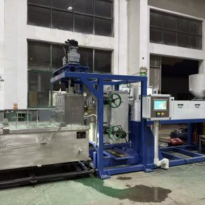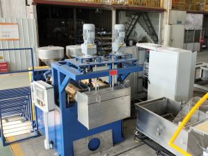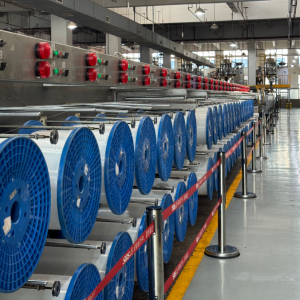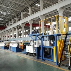
Stable diameter isn’t just a “die problem.” In most plants, diameter variation shows up as a chain reaction:
small flow swings at the die become thick/thin sections
uneven cooling turns into ovality (out-of-round)
tension hunting in drawing amplifies both
winding problems appear last — but get blamed first
This article breaks stable diameter in monofilament production down into a few simple control loops you can diagnose and stabilize one by one.
Stable diameter in monofilament production starts with control loops, not setpoints
Monofilament diameter control is mainly a ratio outcome: how much polymer you push through the die (mass flow) versus how fast you pull it (take-off / haul-off speed). NLY makes this point directly in its overview of how a drawing line produces consistent filament: stable diameter comes from stable flow, stable temperatures, and stable take-off speeds — not one “perfect” die setting in isolation (NLY’s drawing machine guide).
So instead of chasing one knob, treat the line as linked stability loops.
Pro Tip: When you see diameter “hunting” (up/down cycling), don’t start by tightening winding tension. Work upstream first (melt → quench → draw).
Loop 1 — Melt delivery stability (feed → screw → filtration → die)
If the die is fed with a clean melt at stable pressure and temperature, the strand has a chance to be stable. If not, no downstream section can truly “fix” it — it can only react to it.
What typically destabilizes melt delivery
Inconsistent feeding: bridging, segregation, unstable regrind ratios
Temperature control cycling: zones oscillating instead of holding stable
Filtration loading: screen pack restriction changing backpressure over time
Material condition shifts: moisture-sensitive resins (often PA/nylon and PET) or contamination
Even in generic extrusion, melt pressure variation is strongly tied to dimensional variation because small pressure swings can change output rate. Dynisco’s technical note on melt pressure measurement discusses how head pressure fluctuations correlate with dimensional variation in extrudate (Dynisco “Melt Pressure Measurement: Environmental Effects” (PDF)).
What to watch (trend signals)
For awareness-level control, you don’t need a complex model. Start with trends:
melt pressure trend (stable vs rising vs oscillating)
melt temperature behavior (stable vs cycling)
motor load trend (drifting up can indicate restriction or abnormal load)
If you are upgrading a line, PlasticsToday notes that adding a melt pump (gear pump) after filtration can improve melt pressure stability and flow consistency to the die in single-screw systems, and that inline melt pressure measurement around the screen pack helps detect buildup early .
Loop 2 — Geometry lock-in (die + quench water bath)
The die forms the initial strand. The quench water bath freezes that geometry.
If cooling is uneven, you can get ovality — and that ovality often becomes more obvious after drawing.
NLY summarizes the practical goal well: make cooling repeatable and symmetric, not violent.
Why cooling symmetry drives ovality
If the filament cools faster on one side than the other, you “freeze in” an asymmetric cross-section. During drawing, that asymmetry stretches into visible out-of-roundness.
A simple quench SOP (what operators should verify)
Use this as a fast routine when scrap appears:
Water temperature: confirm setpoint and actual reading; keep it stable over time.
Water level: keep it consistent (mark a reference level).
Circulation: confirm pump performance; check filters/strainers.
Flow near the strand: remove turbulence sources (misdirected inlets, splashing, air entrainment).
Strand path: same entry height/angle, centered path, avoid strand contact.
Submerged guides/rollers: check for scale, roughness, sticking.
This checklist is adapted directly from NLY’s quench stability routine (see NLY’s monofilament extrusion line overview).
For deeper cooling practice, NLY’s cooling-focused article is a good internal reference for teams trying to standardize the quench section as a repeatable SOP (NLY’s water bath cooling guide).
Loop 3 — Draw and tension stability (haul-off / godets)
After quench, drawing determines orientation and properties — but it also amplifies instability.
Draw ratio is a recipe, not a single knob
A draw ratio isn’t just one number. In practice it includes:
stage speed ratios (e.g., V2/V1)
draw-zone temperature window
traction and slip behavior at each godet
tension zoning between sections
If the draw system “hunts” or speed ratios drift during ramps, diameter and properties can drift with it.
Failure modes that show up as diameter problems
tension hunting between zones
slip at rollers/godets (traction changes as surfaces wear or contaminate)
necking / frequent breaks after a speed increase
If you want an operator-friendly way to increase speed without losing control, NLY recommends watching three early-warning trends: melt pressure trend, inline diameter trend, and zone tension trend (NLY’s output-without-instability guide).
Winding affects package quality and can introduce tension spikes. But it is usually a late-stage loop.
If you try to “fix diameter” by tightening winding tension, you may temporarily hide a melt/quench/draw instability — and increase break risk later.
A practical rule from NLY’s line-stability guidance: when diameter problems appear, work upstream first (quench, draw synchronization, melt stability) and use winding tension to fine-tune package quality, not as the main diameter controller.
Measurement — what inline diameter control can and cannot do
Inline measurement (often laser-based) is valuable because it turns “we think it’s drifting” into a real trend.
But measurement is not magic:
Small drift can often be corrected by fine speed adjustment.
Fast oscillation usually means an upstream instability is driving the variation.
A simple, practical view (even from smaller-scale filament systems) is that once the process becomes too unstable, the puller mechanism cannot correct thickness reliably (3devo’s note on inconsistent filament diameter). Industrial lines have more tools — but the principle still holds.
A simple troubleshooting order (what to check first)
When stable diameter in monofilament production is the goal, most plants shorten troubleshooting time by using a consistent order:
Melt stability: pressure/temperature trends, feeding consistency, filtration loading
Quench stability: water temperature/level, symmetry, turbulence near strand, strand path centering
Draw stability: speed ratio stability, slip indicators, temperature window
Winding stability: tension logic, traverse, package build checks
This is consistent with NLY’s recommended “work upstream first” logic across the line (NLY’s cooling/stretching/winding process overview).
How NLY designs for stable diameter (short technical view)
Stable diameter is not one component — it’s design choices that support repeatability.
In NLY’s approach to monofilament lines, the “stable diameter” goal is supported by:
process-oriented melt delivery: stable temperature profiling and the ability to manage filtration/loading so melt pressure doesn’t oscillate
quench design for repeatable, symmetric cooling: stable water temperature, flow distribution, and a controlled strand path
draw section stability: speed synchronization across stages and controllable draw recipes (ratios + thermal window)
monitoring integration: using trend signals (pressure/diameter/tension) to detect the edge of stability early
If you want the stage-by-stage line context (drying → extrusion → quench → drawing → heat-setting → winding), NLY’s process walkthrough is a useful reference (Monofilament extrusion process: step by step).
Next steps
If you share your target diameter range, resin (PA/PET/PP/PE), output target, and your top failure mode (drift, ovality, breaks, surface marks), NLY can help you define a practical process window and a trial/FAT plan for stable diameter on your production line.