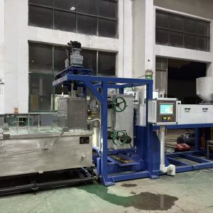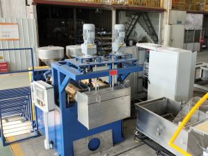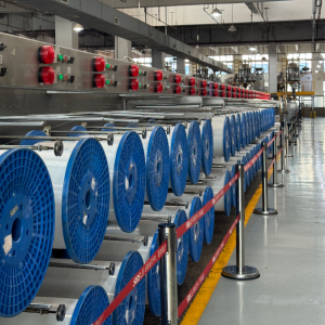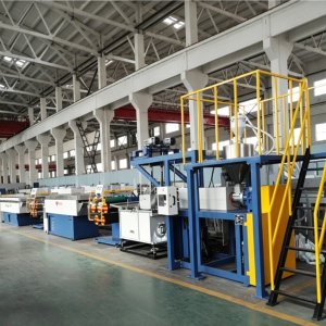
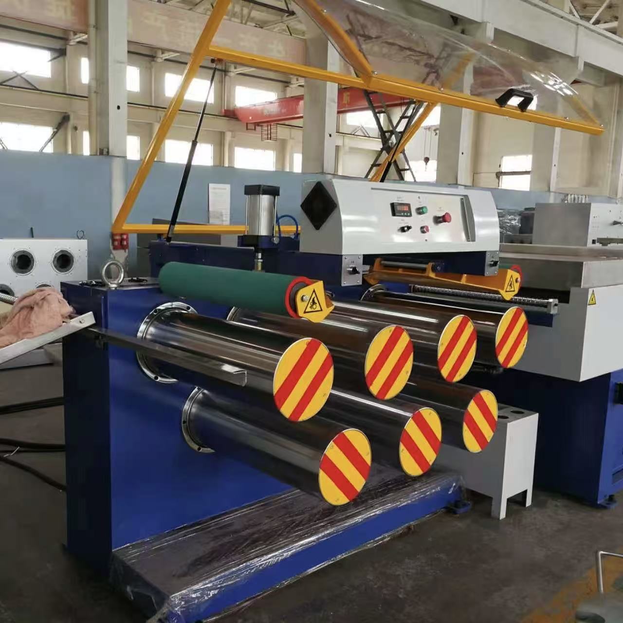
If you’re evaluating a monofilament drawing (stretching) machine, the “roller system” isn’t just a set of cylinders that pull filament forward. It’s a control architecture: surface speed ratios (V1/V2/V3), tension zoning, and a thermal window working together.
When that architecture is right, you get stable diameter and properties at production speed. When it’s wrong, you see familiar symptoms: diameter drift, ovality changes after speed ramps, frequent breaks, and inconsistent spool build.
This article breaks down how a monofilament drawing roller system achieves stable stretching, with a deep focus on multi-stage draw ratio control and what to verify when you compare equipment.
What “draw ratio” means in a roller (godet) system
In a drawing section, “draw” isn’t a vague idea. It’s defined by the surface speed difference between two driven sections.
A practical engineering definition comes from TJWalker + Associates’ web-handling reference, which explains that draw is created by the surface speed ratio between driven rollers, achieved via roller diameter, motor speed/gearing, or a combination of both in the machine design).
The basic V2/V1 picture
V1 = surface speed of the upstream roller set (the “feed” godet)
V2 = surface speed of the downstream roller set (the “draw” godet)
Stage draw ratio ≈ V2 / V1
In plain terms, the monofilament stretching machine draw ratio is the speed ratio that defines how much the filament is elongated in that span.
Key Takeaway: In a stable drawing machine, the roller system’s job is to hold actual surface speeds and their ratio steady—not just the recipe value on the HMI.
Why multi-stage drawing exists (and what it changes)
A single large ratio in one span can work for some materials and product specs—but it can also narrow your stable process window.
A multi-stage roller system spreads the total stretch across two or more controlled spans:
Stage 1 ratio: V2 / V1
Stage 2 ratio: V3 / V2
Total draw (conceptually): (V2/V1) × (V3/V2) = V3/V1
Some production references describe one-step vs two-step stretching as a common approach in monofilament processing, with two-step stretching often used in practice for PET recipes). Treat this as a directional idea—not a universal rule—because your polymer grade, target diameter, and end-use spec decide the right staging.
The stability stack: what the roller system must control (besides the ratio)
Stable drawing usually depends on four layers. Multi-stage draw ratio control is only layer #1.
1) Speed ratio stability: holding V2/V1 under load
A drawing section only performs as well as its drive coordination.
What you want to see:
Ratio control between stages (master/slave or equivalent)
Minimal speed drift when the line accelerates/decelerates
Stable ratio after thermal soak (when temperatures and friction stabilize)
2) Traction: getting “pull” without slip
Even if your drives are accurate, you can still lose stability if the filament slips on the roller surface.
Traction depends on:
Wrap angle (contact length)
More wrap increases frictional grip. Too little wrap can make the system highly sensitive to moisture, finish, or contamination.
Nip/pressure roll strategy
Many draw stands use a nip roll to help thread-up and improve traction. In evaluation, you’re judging whether it produces repeatable traction without damaging the filament surface.
Roller surface condition and cleanliness
Slip is often a “slow failure.” A line might run fine right after cleaning, then become unstable as deposits build up.
3) Tension zoning: separating spans so disturbances don’t spread
A well-designed drawing section behaves like multiple controlled zones rather than one long uncontrolled span.
Typical zones include:
transport after quench
draw span(s)
heat-setting/annealing entry
wind-up/take-up
The point is isolation: if winder tension changes, you don’t want that disturbance to “reach back” into the draw span and change effective draw.
For process context (where drawing and annealing sit in the chain), PLASCO’s overview lists the main stages as extruding → forming → stretching → annealing → winding).
4) Thermal window: drawing at the right temperature, consistently
Stable ratios don’t help if the filament is being drawn outside its workable temperature window.
In practice, this shows up as breaks during a draw-stage speed increase, or property scatter at constant recipe.
How the roller system affects diameter stability and ovality
In a monofilament line, final diameter is the result of upstream melt delivery + quench geometry + drawing stability. If the draw system hunts, diameter will wander even when the extruder looks stable.
Two practical connections matter when you evaluate equipment:
Speed ratio instability becomes diameter variation. If effective draw changes during operation (because V2/V1 drifts or slip changes), the filament is stretched inconsistently.
Disturbances can amplify ovality. Ovality is often driven by asymmetric quenching and alignment, but draw-stage disturbances can make it worse—especially if the filament path is not centered and tension varies through guides.
For full-line context, NLY’s explainer on a plastic monofilament drawing machine is a useful internal reference.
Monofilament drawing roller system evaluation criteria
This is where a consideration-stage buyer wins: you ask how the supplier proves stability—not how they describe it.
Verify actual ratio, not only recipe ratio
Ask for:
commanded speed and measured speed per godet
how the system reports and logs V2/V1 and V3/V2
what happens to ratio during ramps
If a vendor can’t show you trends, you’re relying on hope.
Check stability during acceleration and long steady runs
A stable roller system should hold draw without “hunting”:
during startup and ramp to production speed
after thermal soak
during a long run (when deposits and environmental changes appear)
NLY’s guide on how to increase monofilament line output without losing stability frames output increases as a five-zone stability exercise, with draw-stage synchronization as a core checkpoint.
Ask how traction margin is designed in
Get specific:
wrap scheme (how many wraps, and where)
whether nip pressure is adjustable and how it’s controlled
what surface finish/coating is used and why
cleaning access and expected maintenance intervals
This is also where the godet roller draw ratio becomes real: if the machine can’t maintain traction, your “ratio” is only a number on the screen.
Clarify tension control and what it actually controls
Many quotes mention “tension control,” but tension can be measured and controlled in different places.
Ask:
where tension is measured (between which modules)
whether feedback is used for alarms only, or to trim drive speeds
how tension control in a drawing machine is separated from winder package-build tension
You don’t need proprietary drawings—but you do need a correct system boundary.
Confirm recipe discipline: stability is repeatability
A multi-stage system is only as good as its ability to run the same way across shifts.
Ask for:
recipe management (ratios, temperatures, alarms)
change logging / access levels
what operators are trained to adjust vs what is locked
For a broader list of variables that affect quality (including draw speed synchronization and tension control), NLY’s post on factors that affect plastic monofilament quality is another relevant internal reference.
Next steps: turn your spec into a draw-stage validation plan
If you share your polymer (PA/PET/PP/HDPE), target diameter range, end-use, and output target, a supplier should be able to propose:
number of draw stages
a starting window for stage ratios (V2/V1, V3/V2)
heating/heat-setting configuration
what to measure during FAT (speed ratio trend, diameter trend, break frequency, basic property checks)
As a manufacturer of monofilament extrusion equipment, Changzhou New Liaoyuan Machinery (NLY) can support this type of evaluation by matching a drawing-section configuration to your resin and stability goals, then building a practical sample run / FAT checklist around your acceptance criteria.