Plastics extrusion converts solid thermoplastic resin into continuous profiles, pipes, film, sheet, and specialty strands. It is one of the highest-volume polymer processing methods in use, and for plant managers and engineering teams, understanding how the process works — and where it fails — directly affects throughput, dimensional consistency, and operating cost.
This guide covers the full plastics extrusion process: how each stage works, the main process variants, critical parameters, common defects and their root causes, and the specific demands of monofilament production as a precision application.
How the Plastic Extrusion Process Works
Plastics extrusion is a continuous process. Solid material enters one end of the extruder; a shaped, solidified product exits the other. The sequence is feeding → melting → pressurizing → shaping → cooling → haul-off. Each stage has its own failure modes, and problems in an upstream stage always propagate downstream.
Material Feeding and Preparation
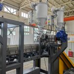
Pellets, granules, flakes, or powder fall by gravity from a hopper into the extruder barrel. Many hygroscopic resins — particularly PET and nylon — must be dried to a defined moisture target before processing. Residual moisture turns to steam in the melt, causing bubbles, porosity, and hydrolytic chain scission that permanently reduces molecular weight and mechanical properties in the finished product.
Gravimetric feeders are the standard where additive accuracy matters. Colorants, stabilizers, fillers, and flame retardants are dosed here. The extruder receives a metered, premixed stream rather than hand-blended raw material.
Melting and Conveying
The rotating screw conveys material forward through three functional zones along the heated barrel:
Feed zone: Solid material compresses and begins picking up heat from the barrel wall. Friction between material and barrel is a significant heat source at this stage.
Transition (compression) zone: The screw channel depth decreases, compressing and shearing the partially melted material. Shear heat is the primary melting mechanism for most resins.
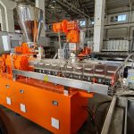
Metering zone: The melt is homogenized and pumped at controlled pressure toward the die. This zone sets output rate per revolution.
Screw geometry — L/D ratio, compression ratio, and mixing section design — is matched to the resin. A barrier screw for PET performs very differently from a general-purpose screw designed for PP, and running mismatched geometry is a reliable path to quality problems.
Melt Filtration and Pressure Buildup
Before the melt reaches the die, it passes through a breaker plate and screen pack. Screens remove solid contaminants and break up incompletely plasticized material. They also build back pressure, which improves melt homogeneity. A steadily rising pressure differential across the screen pack signals loading — the screen needs a change.
Some precision lines add a melt pump (gear pump) between the extruder and die. The pump decouples output rate from screw speed, delivering highly stable melt pressure to the die. For diameter-critical applications such as monofilament and medical tubing, this stability is often worth the added complexity.
Die Shaping
The die shapes the melt into its product cross-section. Die geometry, flow channel balance, land length, and die gap all influence the extrudate. The melt exits the die lip and immediately swells — die swell — as the polymer’s elastic memory relaxes. The magnitude of this swell is resin- and temperature-dependent and must be designed into die tooling.
For pipe and tube, a mandrel inside the die forms the bore. For monofilament, a spinneret plate with precision-bored holes produces individual melt strands. For sheet and film, a flat (T-die) forces a wide, thin melt curtain.
Cooling and Solidification
Cooling rate determines crystallinity, mechanical properties, and dimensional stability. The method depends on product type:
Water quench bath: Standard for monofilament, rod, tube, and pipe. Bath temperature controls quench rate and crystallinity development.
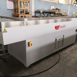
Vacuum calibration and water cooling: Used for pipe and rigid profile. A sizing sleeve or calibration basket holds dimensions while cooling removes heat.
Air cooling with chill rolls: Used for sheet and cast film. Melt exits the die onto a cooled roll stack.
Air ring (blown film): An air ring surrounds the inflated bubble and controls cooling rate, frost line height, and bubble stability.
Uneven cooling is one of the most common root causes of warpage, ovality, and thickness variation. Cooling system design deserves as much attention as the extruder specification.
Haul-Off, Drawing, and Finishing
Caterpillar haul-off units pull the extrudate from the die at a controlled speed. The ratio of haul-off speed to die output rate defines drawdown — how much the cross-section reduces from die gap to final product dimension. For monofilament, post-extrusion drawing is a deliberate additional step that orients polymer chains and builds tensile strength.
Flying saws, rotary cutters, or guillotines cut continuous profiles to length. Monofilament and yarn products wind onto spools or bobbins.
Types of Plastic Extrusion
Plastics extrusion branches by die geometry and cooling method. Each variant has distinct equipment requirements and applications.
Type | Product form | Common materials | Key applications |
|---|---|---|---|
Profile | Fixed cross-section | PVC, PP, ABS | Window frames, weatherstrip, construction trim |
Pipe / tube | Hollow cylindrical | PVC, HDPE, PEX, PA | Plumbing, industrial hose, medical tubing |
Sheet | Flat, ≥ 0.25 mm | PP, PET, ABS | Thermoforming feedstock, packaging sheet |
Cast film | Flat thin web via T-die | PP, LLDPE, EVA | Packaging film, cast laminate |
Blown film | Inflated bubble | LDPE, LLDPE, HDPE | Bags, stretch film, agricultural film |
Coextrusion | Multi-layer structure | Compatible polymer pairs | Barrier packaging, multilayer pipe |
Monofilament | Single solid strand | PET, PA, PP, PE, PBT | Brush bristles, fishing line, zipper, mesh |
Extrusion coating | Coating onto substrate | LDPE, PP, EVA | Wire insulation, paper/foil coating |
Each type requires purpose-built downstream tooling. A pipe line cannot simply be converted to monofilament production by swapping the die — the entire downstream, including cooling, drawing, and winding, is product-specific.
Materials and Processing Requirements
Plastics extrusion primarily processes thermoplastics, because they melt repeatably within defined temperature windows. The key resins and their processing characteristics:
PET (polyethylene terephthalate): Melt temperature 275–295 °C, strict drying requirement (≤ 50 ppm moisture). Highly susceptible to hydrolytic degradation from residual moisture. Primary material for monofilament, sheet, and strapping.
PA (nylon 6, 6/6, 6/12): Strongly hygroscopic; must be dried to < 0.1% moisture for most grades. Viscosity is sensitive to temperature variation. Used for brush bristle monofilament, technical tubing, and engineered profiles.
PP (polypropylene): Low moisture sensitivity, wide processing window, but susceptible to oxidation at elevated temperatures. Antioxidant stabilization is important for long residence times. Used for raffia tape, monofilament yarn, pipe, and film.
PE (HDPE, LLDPE, LDPE): HDPE is the standard for pressure pipe. LLDPE and LDPE are the primary blown film resins. Each grade carries a different melt flow index (MFI) matched to the line design — substituting grades without confirming compatibility is a common source of output instability.
PVC: The narrowest processing window of the common resins. Degradation above the processing temperature is rapid and releases corrosive HCl. Heat stabilizer selection is critical. uPVC for rigid profiles and pipe; flexible PVC (with plasticizer) for wire insulation and flexible profiles.
Additives — stabilizers, lubricants, fillers, colorants, flame retardants — modify both processing behavior and end-use performance. Incorrect additive loading is one of the more overlooked root causes of die buildup, screw fouling, and extrudate defects.
Critical Process Parameters
Output stability depends on controlling a short list of interdependent variables. According to Plastics Technology’s guide to collecting and interpreting extrusion process data, the three most actionable signals are melt pressure, melt temperature, and motor load. If any oscillates, everything downstream — diameter, wall thickness, surface quality — oscillates with it.
Parameter | Typical control range | What it governs |
|---|---|---|
Barrel temperature profile | Zone-by-zone, resin-specific | Melt viscosity and homogeneity |
Die temperature | ±1 °C for precision lines | Die swell and surface quality |
Screw speed | 20–120 RPM for most applications | Output rate and shear heat |
Head pressure | Application-specific | Melt mixing quality and screen pack load |
Haul-off / line speed | Synchronized to extruder output | Drawdown ratio and final dimensions |
Quench / cooling temperature | Resin-specific | Crystallinity and property development |
For hygroscopic resins and diameter-critical products, barrel zone tolerances of ±1–2 °C are typically required. Wider swings cause viscosity variation that feeds through to dimensional inconsistency. The zone-by-zone implications of temperature control — including thermocouple placement and PID tuning — are covered in depth in the engineering guide to temperature control in the extrusion process.
Common Defects and Troubleshooting
Most extrusion defects trace back to four root-cause categories: material condition, temperature imbalance, mechanical wear, and speed mismatch. Diagnosing from symptom to root cause is faster than adjusting parameters at random.
Defect | Most likely cause | First checks |
|---|---|---|
Melt fracture / shark skin | Excessive shear, low die temperature, high output | Lower screw RPM; raise die temperature; confirm resin MFI matches line spec |
Bubbles / porosity | Moisture in feed material | Verify drying temperature and time; check dew point of drying air |
Surging / diameter variation | Screen pack loading, feeder inconsistency, screw wear | Monitor head pressure trend; calibrate feeder; inspect screen differential |
Discoloration / black specks | Thermal degradation, hot spots, long residence time | Check zone temperatures; clean die and barrel dead zones; reduce residence time |
Warpage / distortion | Uneven cooling, asymmetric die flow | Balance cooling flow rates; check die land symmetry |
Fish eyes / gels | Contamination, insufficient plasticization | Inspect and replace screen pack; verify resin quality |
Surface lines / streaks | Die lip damage, carbon buildup | Clean and inspect die lip; check for buildup at land |
Wall eccentricity (pipe) | Die/mandrel misalignment, cooling imbalance | Re-center die; balance cooling water distribution |
Pro Tip: When a defect produces multiple simultaneous symptoms — for example, both bubbles and discoloration — the most likely culprit is material condition. Check drying and contamination before touching machine settings.
Monofilament-specific: diameter oscillation at a repeatable frequency usually points to screen pack loading (pressure-driven) or feeder pulsing (output-driven). Head pressure trending upward with stable screw speed confirms the screen — not the screw — is the constraint.
Monofilament Extrusion: A Precision Filament Application
Monofilament extrusion applies the same fundamental plastics extrusion principles but adds a downstream sequence — quenching, multi-stage drawing, heat-setting, and precision winding — that defines the final mechanical properties and dimensional accuracy of each strand.
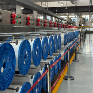
The production flow runs: material conditioning → extrusion → melt filtration → spinneret / die → quench water bath → take-off / godets → drawing stages → heat-setting / annealing → oil treatment (where required) → winding. Diameter at the spinneret is only the starting point; the draw ratio applied in subsequent stages is what builds tensile strength and locks in the final diameter. As the monofilament extrusion process step-by-step guide explains, feeding consistency, quench bath stability, and draw-speed synchronization are the three variables most directly responsible for output quality.
End uses include toothbrush and cosmetic brush bristles, industrial brush filament, zipper monofilament, fishing line, agricultural and filtration mesh, and synthetic grass. Each application imposes different constraints on diameter tolerance (often ± 0.005 mm or tighter), surface finish, tensile strength, and elongation at break — which is why monofilament lines are typically configured for a specific resin and application rather than run as general-purpose systems.
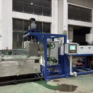
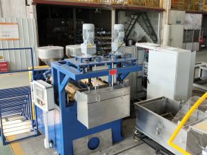
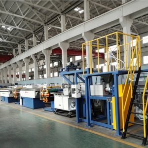
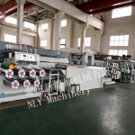
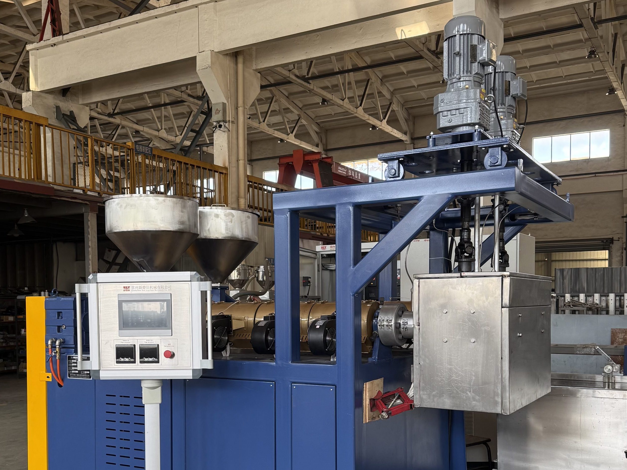
NLY Machinery, founded in 1989 and serving manufacturers in over 20 countries, designs and builds complete monofilament extrusion lines for PET, PA6, PA66, PP, and PE. For teams scoping a new line or replacement system, the overview of what a plastic monofilament extrusion line includes provides a systems-level reference for understanding the full production chain before engaging suppliers.
Evaluating a Plastics Extrusion Machine: Criteria That Matter
The extruder is one component of a complete line. When specifying equipment, the downstream tooling, control system, and after-sales support are equally important. Criteria that apply across most line types:
Screw and barrel specification: L/D ratio, compression ratio, and screw design must match the target resin and output rate. Request the screw drawing and material specifications. For abrasive compounds (filled resins, recycled material with fines), a bimetallic barrel significantly extends service life.
Temperature control system: Confirm the number of controlled zones, controller type (PID is standard for precision applications), and achievable stability. ±0.5–1 °C zone stability is the expectation for diameter-critical lines. Sensor type and placement affect both accuracy and responsiveness.
Drive system: AC vector drives maintain stable torque at low screw speeds — important for melt quality during startup and speed transitions. Servo drives are used where precise speed synchronization across multiple line sections is required.
Screen changer type: Manual bolt-change changers are cost-effective for less demanding applications. Continuous-type (double-bolt or hydraulic slide) screen changers maintain production during screen changes — necessary for lines where a pressure spike would cause breakage or dimensional upset.
Downstream completeness: Request the full line layout, not just the extruder specification. Cooling system capacity, haul-off design, and winding tension control all affect final product quality and are often where lower-cost lines compromise.
After-sales support: Consumable parts availability (screws, barrels, heater bands, thermocouples), remote commissioning capability, and operator training options. Spares lead time directly affects MTTR on a continuously running production line.
For high-output lines, specific energy consumption (kWh/kg) is worth including in the evaluation. The engineering guide to reducing extrusion energy consumption covers the primary levers — drive efficiency, barrel insulation design, screw geometry, and cooling optimization — at a level of detail useful for supplier conversations.
Next Steps
The gap between a stable, profitable extrusion line and one that produces chronic scrap comes down to consistency: disciplined material preparation, tight process parameter control, and a systematic approach to defect diagnosis. These are not exotic disciplines — they are standard practice on well-run lines.
If you are evaluating a new monofilament extrusion line or assessing a replacement for aging equipment, contact NLY Machinery to discuss your resin selection, target diameter range, and end-use application. With over 35 years of specialization in monofilament extrusion, the team can configure a complete line to your production requirements and support installation, commissioning, and first-run qualification.