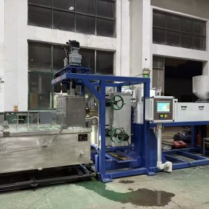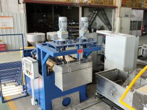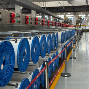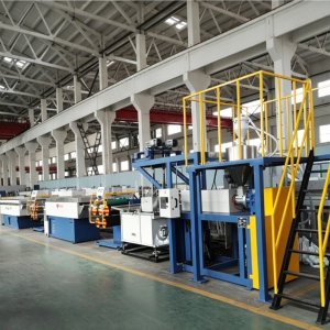
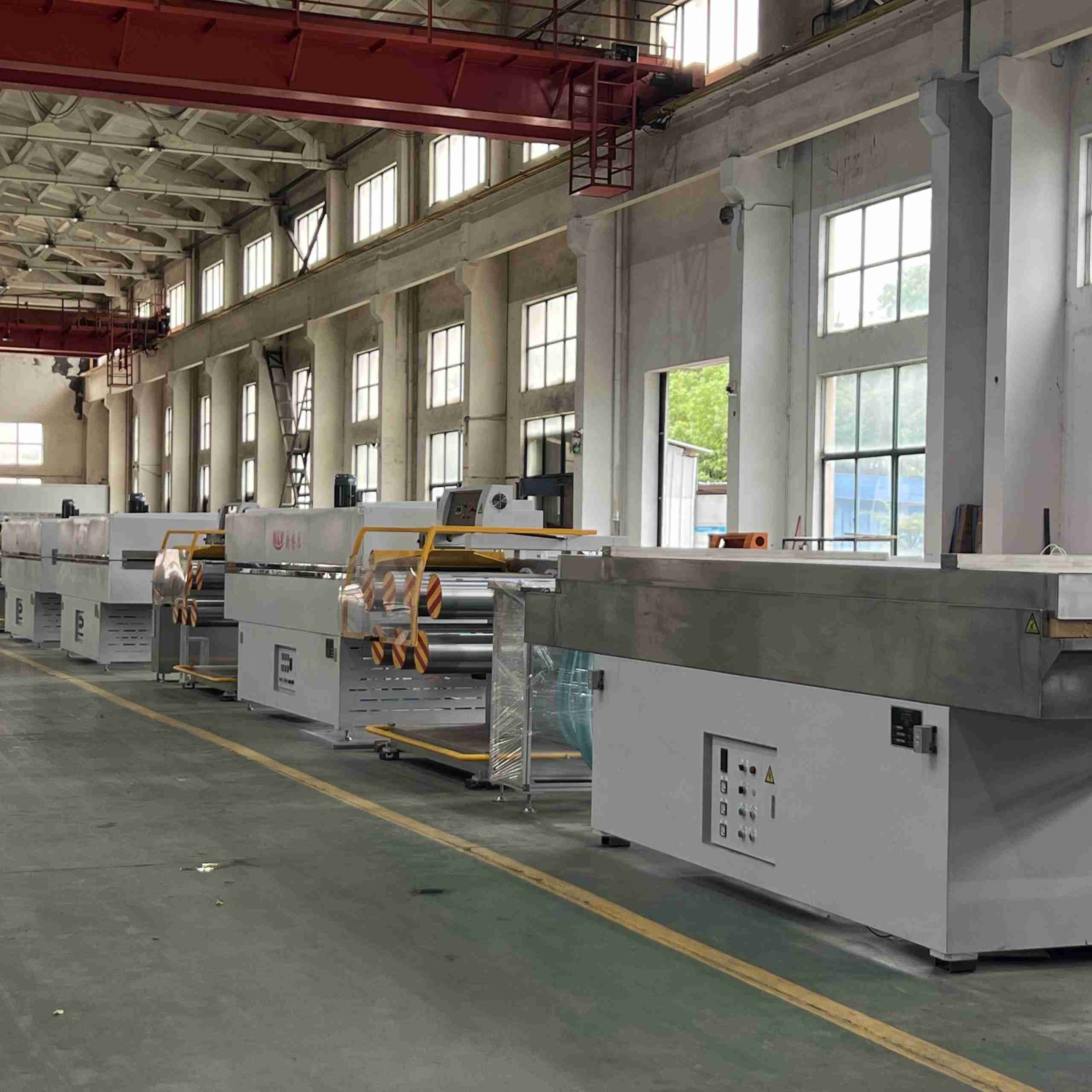
Picture a spool of monofilament sitting in a shipping crate. It looks simple: one long plastic strand wound neatly into a coil. Getting that strand to hold a precise diameter, stay round, and keep its strength across the whole spool is not simple at all. It takes a connected line of machines, each with one job to do.
That line is what monofilament extrusion is: you feed polymer pellets in one end and pull out a continuous, single filament on the other. The logic in between is: melt the plastic into a stable liquid, form it into a strand, freeze that shape, then stretch and stabilize the strand until it hits the diameter and properties your product needs.
This post walks through each stage of how monofilament extrusion works — what physically happens at every step and, just as important, which failure mode that step controls. If you already run a line, the second half gives you a symptom-to-cause map that cuts down guesswork.
A mental model: pellets in, a controlled strand out
Before touching any knob, it helps to hold one simple picture: dry the resin → melt it → form it → cool it → stretch it → stabilize it → wind it. The monofilament extrusion process is a conveyor of control, and each zone hands a more finished product to the next one.
The reason plants describe it as a system rather than a single machine is that quality is not made in one place. A defect that shows up at the winder often started three stages earlier. That is why experienced operators think in linked stability loops — melt delivery → shaping and cooling → drawing → heat setting → winding — instead of checking one knob at a time.
Stage 1: Drying and feeding
Monofilament extrusion starts before the plastic is even melted. Most thermoplastics — especially nylons (PA6, PA66, PA612) and PET/PBT — absorb moisture from the air. If that water reaches the melt, it turns to steam and shows up as bubbles, voids, and weak spots in the strand.
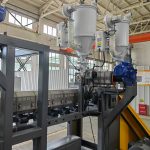
The drying stage removes that moisture. For hygroscopic resins this is critical: many lines use a desiccant dehumidifying dryer targeting a very low moisture level (for PET and nylon, well under 0.05% by weight, often verified by a dew point of −40°C or lower). Feed consistency matters just as much — if the hopper starves or the regrind ratio drifts, the melt flow downstream pulses.
Key Takeaway: Drying is not a “nice to have” for nylon and PET. Wet resin is the classic first suspect when a fine strand looks foamy or brittle straight off the line.
Stage 2: Extrusion and melt delivery
The extruder is the engine of the line. Its job is simple to state and hard to execute: deliver a clean, uniform melt at a stable temperature and pressure to the die.
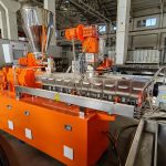
Inside a single-screw extruder, the screw works through three functional zones: a feed zone that conveys solid pellets, a transition (compression) zone where the solid melts and becomes continuous, and a metering zone where the screw acts as a pump feeding the head. On many monofilament lines a gear melt pump is added after the extruder to smooth out flow pulsation, so the die sees steady throughput rather than screw-driven surges.
What you watch here are process variables, not just setpoints: the melt pressure trend and melt temperature behavior. Rising pressure often means filtration (screen pack) is loading up; pressure oscillation usually shows up downstream as diameter drift.
Pro Tip: Treat pressure trend and temperature stability as your early-warning system. They move before diameter does.
Stage 3: Die and quench bath — where geometry locks in
The molten melt now passes through the die (called a spinneret on fiber-style lines) — a plate drilled with the holes that shape each strand. Right after the die, the hot strand enters a quench water bath to solidify.
This is the stage where roundness is decided. If the strand cools unevenly — faster on one side than the other — an asymmetric shape gets frozen in. That small out-of-round condition is then amplified by drawing, turning into visible ovality. Quench stability is so important that the distance between the die face and the water surface, the water temperature, the level, and the flow pattern all need to be repeatable.
⚠️ Warning: Do not try to “fix” an unstable quench by cranking the draw ratio or winding tension. You will mask the symptom and make the defect worse. Stabilize cooling first.
Stage 4: Drawing — where strength and final diameter are set
Once the strand is solid, the line stretches it. This is the monofilament drawing process: controlled elongation that aligns the polymer chains along the filament axis, which is what gives monofilament its tensile strength and stiffness at a given diameter.
The key number is the draw ratio, created by the speed difference between driven roller sections (essentially downstream surface speed divided by upstream speed). A higher draw ratio generally increases orientation and strength, but it also narrows the stable operating window — push it too far and the strand snaps. Many lines use multi-stage drawing (multiple roller sets and heated zones) precisely to widen that stable window and reach higher total ratios without breaking.
Breaks in the drawing section are one of the fastest ways to lose uptime. But the cause is often upstream — an uneven temperature profile from a poor quench, or weak spots from moisture or contamination — rather than the draw section itself.
Stage 5: Heat setting and annealing — locking in stability
After drawing, the filament carries internal stress. If you wound it immediately, that stress could release later — showing up as shrinkage, curl, or coil “memory” during storage or in your customer’s process.
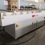
Heat setting (annealing) relaxes that stress. The drawn filament passes through a heated zone — hot air oven or heated godet rolls, often under controlled tension — so it comes out dimensionally stable. This is what keeps the strand’s diameter and behavior consistent across spools, shifts, and weeks of storage.
Stage 6: Winding — building a usable package
Finally, the finished monofilament is wound onto spools or reels under controlled tension and a consistent traverse.
Winding is the last control loop, not the first place to fix problems. If the strand is still too warm, or tension is hunting because stage speeds are unsynchronized, the package comes out with telescoping edges, loose layers, or crushed layers — none of which are winding’s fault. Treat it as the handoff: winding packages the quality the earlier stages produced, and it can only destroy it, not create it.
Common misconceptions about monofilament extrusion
Most people who are new to the monofilament extrusion process carry the same few wrong ideas. Clearing these up early saves real troubleshooting time.
“The die alone sets the final diameter.” The die sets the initial strand, but the final diameter depends on downstream drawing, quench behavior, and pull speed. The die is the start, not the whole answer.
“Cooling is just a cleanup step.” Quench cooling is structural — it locks in the geometry and internal state that drawing then builds on. Unstable cooling shows up later as ovality and drift.
“Every defect is a melt or die problem.” Ovality, bubbles, rough surface, and breaks can all start in drying, filtration, draw stability, or heat setting. Symptom-first thinking points you to the right zone.
“Monofilament is any filament.” Monofilament means one solid strand. Multifilament yarns bundle many fine filaments. The line, the hardware, and the control priorities differ.
Troubleshooting map: symptom → where to look first
When a line misbehaves, start with the zone that can physically create the defect you see. This map is adapted from common plant-floor practice and NLY’s factors that affect plastic monofilament quality.
Symptom | Most likely upstream driver | First check |
|---|---|---|
Diameter drift over time | Melt instability, feeding swings, quench drift, tension swings | Melt pressure trend, feeding consistency, quench temperature |
Ovality / out-of-round | Quench asymmetry, die-to-bath alignment, off-center path | Quench symmetry + water level, strand alignment, die cleanliness |
Bubbles / voids | Moisture in resin | Drying discipline, resin exposure, regrind handling |
Breaks in drawing | Uneven temperature profile, aggressive draw ratio, weak spots | Quench stability first, then draw speed sync |
Shrinkage / coil memory | Insufficient heat setting | Heat-setting temperature and residence time |
Specks / gels / surface lines | Contamination, filtration, die deposits | Filtration discipline, resin cleanliness, die condition |
If you want to go deeper on the drawing section — the stage where strength and diameter are actually made — NLY’s guide to monofilament drawing and orientation breaks down draw ratios and temperature windows material by material.
How the full line fits together
Stepping back, the whole point of monofilament extrusion is control. Every stage either sets a physical property (diameter, roundness, strength, dimensional stability) or protects the stages after it (stable melt feed, clean filtration, repeatable cooling). When one stage drifts, the downstream stages amplify it.
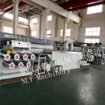
That is why the same strand can look fine coming off the die yet fail at the winder — and why the fix is almost never a single magic setting. NLY’s line overview explains how the whole system is designed and tuned as connected stability loops rather than standalone machines.
Next steps
If you are planning a new line or validating an existing one, you do not need to start from guesswork. Working from a few inputs — polymer (PA/PET/PP/PE/PBT), target diameter range, target output, and your end-use (brush, zipper, net, rope) — you can map a practical line configuration and startup checklist: drying discipline, melt filtration, quench control, multi-stage draw ratio, and heat setting.
To see typical equipment configurations, you can browse monofilament extrusion machines from NLY, then request a custom line layout proposal or a Factory Acceptance Test (FAT) sample run to validate the process on your material before you commit.