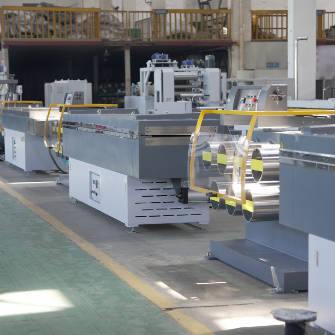
A plastic monofilament extrusion line is one of those systems that looks simple on paper—pellets in, filament out—but behaves like a chain of control loops on the plant floor.
If you’re seeing diameter drift, out-of-round (ovality), breaks in the draw section, or unstable winding, it usually isn’t “one bad setting.” It’s the line behaving exactly like a coupled system: what happens in melt delivery shows up at the die, what happens in quenching gets amplified in drawing, and what happens in tension control shows up as package defects.
This article explains what a plastic monofilament extrusion line is, what each section is responsible for, and why the most common stability problems happen.
What a plastic monofilament extrusion line is
A plastic monofilament extrusion line is a continuous production system that turns polymer resin (pellets, granules, sometimes flakes) into a single solid strand (monofilament) with controlled diameter, roundness, surface condition, and mechanical behavior.
It helps to separate two ideas:
A plastic monofilament extruder is the “engine” that melts and pressurizes polymer.
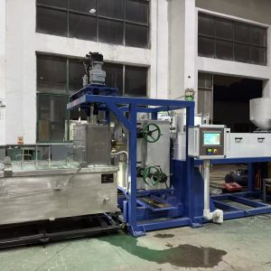
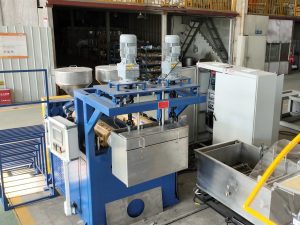
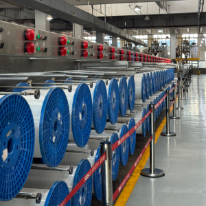
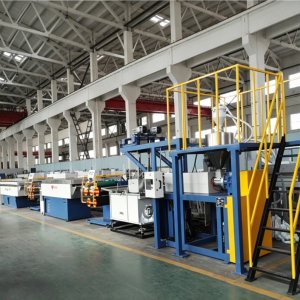
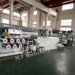
A monofilament extrusion line is the whole system that makes the strand usable: extrusion + shaping + cooling + drawing + heat-setting + winding.
If you want a baseline definition of extrusion as a general manufacturing process (hopper → melting → filtration → die → cooling → take-off → winding/cutting), this overview of plastic extrusion is a solid starting point.
The line as a system: five stability loops
A practical way to think about a monofilament extrusion line is “five stability loops.” Each loop has a primary control job—and a typical failure pattern.
This system chain is often described as melt delivery → shaping/cooling → drawing/orientation → heat-setting → winding (see the explainer on the monofilament extrusion process).
Here’s what that looks like in plant terms:
Melt delivery stability: deliver a clean, uniform melt at stable pressure and temperature to the die.
Geometry lock-in (die + quench): freeze the strand symmetrically so roundness doesn’t get “baked in” as ovality.
Orientation (drawing): apply controlled stretching (draw ratio) to hit strength/stiffness without breaks.
Stress control (heat-setting/annealing): reduce internal stress so shrinkage doesn’t show up later.
Tension + package control (winding): build a stable package without flattening, telescoping, or tension hunting.
If your troubleshooting jumps straight to the last station (winding tension), you’re often correcting symptoms, not causes.
Extruder + melt delivery: the “clean, stable melt” job
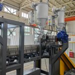
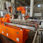
The extruder section’s job is simple to say and hard to execute: melt the polymer, mix it, pressurize it, and feed the die with steady flow.
Inside a typical single-screw extruder, you can think in three functional zones:
Feed zone: solids enter via hopper/feed throat and start conveying.
Transition (compression) zone: solids melt and the melt becomes continuous.
Metering zone: the screw acts as a pump to deliver uniform melt to the head.
This breakdown of the plastic monofilament extruder working principle focuses on what the extruder section must do to keep melt delivery stable.
Where instability starts (feeding, pressure trends, filtration)
In monofilament, small instabilities show up fast because downstream sections amplify them.
Common upstream instability drivers include:
Inconsistent feeding (bridging, segregation, inconsistent regrind ratio): shows up as output pulsation.
Temperature control cycling (heating and cooling fighting each other): shows up as viscosity swings, pressure swings, and unstable melt quality.
Filtration loading (screen pack restriction): shows up as a rising head/adaptor pressure trend.
Pro Tip: Watch trends, not only setpoints. A stable controller number doesn’t guarantee stable melt at the die.
At awareness stage, the key idea is simple: if you want stable filament, treat melt pressure trend and melt temperature behavior as process variables, not just “machine settings.”
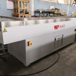
Die + quench water bath: the “lock-in geometry” job
The die (sometimes called a spinneret in fiber-style lines) creates the initial strand geometry. The quench water bath then freezes that geometry.
This is where a lot of “mysterious” problems become predictable:
If cooling is uneven, you can get ovality.
If the strand enters the bath inconsistently, you can get drift and tension swings.
If the strand is too soft when it meets any guide/roller, you can get deformation and surface marks.
PLASCO notes in its monofilament extrusion process overview (2023) that monofilament diameter depends not only on die-hole size, but also on factors like the distance between the die and the water interface.
Why quench symmetry drives ovality
Most “ovality control” work is really quench symmetry + alignment.
If the strand cools faster on one side than the other, you freeze in an asymmetric structure. Then the drawing section stretches that asymmetric structure—and the ovality becomes more obvious.
That’s why many operators do not chase ovality by immediately changing draw ratio. They stabilize cooling first.
Quench stability checklist (use before you touch draw settings)
This water-bath guide includes a practical checklist you can turn into a one-shift SOP: water bath cooling checklist.
Use it as a fast control routine:
Confirm water temperature setpoint and actual reading and keep it stable over time.
Keep water level consistent.
Confirm circulation pump performance; check filters/strainers.
Remove obvious turbulence sources near the strand (misdirected inlets, splashing, air entrainment).
Keep strand entry height/angle and centered path consistent; avoid strand contact.
Inspect submerged guides/rollers for scale, roughness, or sticking.
One useful cooling concept: what matters is often the boundary layer at the surface. The article “Extrusion Cooling: It’s All About Turbulence” (Plastics Technology, 2017) explains why localized turbulence at the heat-transfer surface (using jets/baffles/bubblers) can improve cooling—especially in large tanks where bulk flow is hard to control.
The point is not “make the bath violent.” The point is: make cooling repeatable and symmetric.
Drawing + heat-setting: the “set properties and shrinkage” job
After quenching, monofilament is usually drawn (stretched) to align polymer chains. This is commonly called the monofilament drawing process.
Drawing is where you move from “a strand that exists” to “a strand that has the properties you actually need.”
What draw ratio really means
In roller-based systems, draw ratio comes from the speed difference between driven sections.
In practical terms:
Higher draw ratio generally increases orientation (strength/stiffness), but narrows your stable window.
If the strand temperature profile is uneven (often due to quench instability), draw becomes unstable.
If you’re seeing frequent breaks, the draw section is often where uptime is lost fastest—so it pays to stabilize what’s feeding into it.
What heat-setting prevents
After drawing, the filament can contain internal stress. Heat-setting (annealing) under controlled tension helps relax that stress so you don’t get shrinkage surprises later (during winding, storage, or downstream use).
Winding: packaging that can still create defects
Winding is not just “put it on a spool.” It’s a controlled tension process that creates a package the next process can unwind reliably.
If winding is unstable, you may see telescoping packages, loose edges, flattening/marking, or inconsistent hardness across spools.
But here’s the trap: winding problems often originate upstream.
If the strand is still too warm/soft, winding tension can deform it.
If tension is hunting because stage speeds aren’t synchronized, winding sees a moving target.
If diameter is drifting, package build becomes inconsistent.
Treat winding as the last control loop, not the first one.
Quick troubleshooting map: what you see → where to look first
Use this as a fast “don’t guess” map before changing recipes.
What you see | Most likely upstream drivers | First checks |
|---|---|---|
Diameter drift over time | melt instability, feeding swings, quench temperature drift, tension swings | melt pressure trend, feeding consistency, quench temp stability, speed synchronization |
Ovality / out-of-round | quench asymmetry, die-to-bath alignment, strand path off-center, turbulence near strand | quench symmetry + water level, strand alignment, guide condition, die cleanliness |
Frequent breaks in drawing | unstable quench/temperature profile, aggressive draw ratio for the window, speed mismatch | quench stability first, draw section speed sync, heat-zone stability |
Surface marks / haze / specks | dirty water/scale, strand contact, filtration issues | water filtration/cleanliness, submerged guides/rollers, melt filtration discipline |
For a deeper defect-to-driver breakdown, see factors that affect plastic monofilament quality.
Next steps
If you’re new to monofilament lines, the fastest way to move from “reading” to “stable production” is to define your process window in one page:
polymer(s) (PP/PE/PET/PA, virgin vs recycled)
target diameter range and tolerance
target output (kg/h) and expected uptime
top defects you must eliminate (ovality, drift, surface marks, breaks)
If you want, Changzhou New Liaoyuan Machinery (NLY) can help translate that into a line layout and a stability-first trial plan—what to measure in extrusion, quench, drawing, and winding during a run.