If you run a monofilament line, “extrusion” and “drawing” can sound like two names for the same thing: you push polymer through a die, you pull it downstream, you wind it.
But they’re not the same process. And mixing them up leads to the most common troubleshooting mistake on a line: adjusting the draw section to fix an extrusion problem (or adjusting the extruder to fix a draw instability).
This article gives you a practical distinction you can use on the shop floor.
Quick definitions (in plain language)
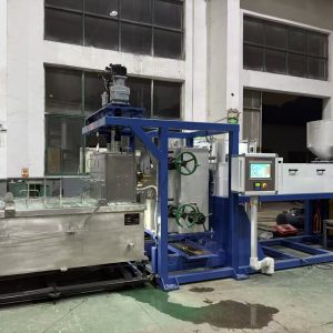
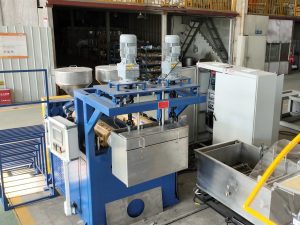
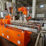
Extrusion is the step where you melt the polymer and form the initial strand shape by pushing the melt through a die. As NLY defines it, plastic extrusion is a continuous process where thermoplastic material is melted, pressurized, and pushed through a shaped die to form a long product with a constant cross-section.
Drawing is the step where you stretch the already-formed strand (after quenching) using controlled speed ratios between rollers.
In monofilament lines, you’ll also hear “draw section,” “drawing roller system,” or “drawing process in monofilament production” used to describe this controlled stretching zone.
The purpose is to orient polymer chains and set mechanical properties.
In other words:
Extrusion controls melt quality and initial geometry.
Drawing controls molecular orientation and (therefore) final properties.
Difference between extrusion and drawing process: what’s different
Here’s the simplest comparison that’s still technically accurate.
Dimension | Extrusion | Drawing |
|---|---|---|
Material state | Molten polymer melt | Solid/semi-solid filament (often heated, but not melted) |
Primary “job” | Shape the strand through the die | Stretch the strand to orient molecules |
Main controls | Barrel temps, screw speed, melt pressure, filtration, die | Draw ratio (speed ratios), traction/slip, thermal window, tension zoning |
What it most affects | Diameter baseline, surface condition, melt stability | Strength/stiffness, elongation, shrinkage tendency, break stability |
Typical symptoms when unstable | Pressure surging, diameter drift, gels/specks, surface melt defects | Frequent breaks, property scatter, necking instability, tension/winding defects |
For a broader concept definition, see Plastic extrusion (Wikipedia) and Drawing (manufacturing) (Wikipedia).
What extrusion actually does in a monofilament line
In monofilament production, extrusion is not “just pushing plastic.” It’s the system that must deliver a steady, uniform melt to the die.
The extrusion section’s real output is melt stability
A stable extrusion section means:
the polymer is fully plasticized (no unmelted particles)
melt temperature is stable (no cycling that changes viscosity)
melt pressure trend is stable (no surging)
filtration is doing its job (contaminants removed, no sudden restriction)
In NLY’s monofilament line framing, the extruder is the “engine” that melts and pressurizes polymer, and melt stability upstream shows up downstream as diameter and tension problems if it’s not controlled. See the NLY guide on how a plastic monofilament extrusion line works for the system view.
Typical extrusion-driven issues
Extrusion problems tend to be “upstream physics” problems:
Feeding inconsistency → output pulsation → diameter drift
Temperature control cycling → viscosity swings → pressure swings
Filtration loading → rising head/adaptor pressure trend → instability
If your melt delivery is unstable, the drawing section can’t “average it out.” It usually amplifies it.
What drawing actually does (and why it changes properties)
Drawing is where you intentionally stretch the quenched filament. Mechanically it’s simple: you run downstream rollers faster than upstream rollers. Molecularly it’s the most important step for performance.
Drawing = controlled stretching to orient polymer chains
A useful industry explanation is in Zeus’ technical primer, Drawn Fiber: Polymers, Process, and Properties Primer (PDF): extrusion initiates orientation, but drawing further orients polymer chains in the machine direction, allowing closer packing and increasing density and tensile strength.
Practically, that’s why a “drawn” monofilament is often:
stronger and stiffer (more orientation)
less extensible (it’s already been elongated in process)
more sensitive to heat-set conditions (to control shrinkage and residual stress)
Draw ratio: the main knob (but not the only one)
Draw ratio is usually defined by speed ratios between driven rollers (godets). In a simple stage:
Stage draw ratio ≈ V2 / V1
Where V1 is upstream roller surface speed and V2 is downstream roller surface speed.
Many monofilament lines use multi-stage drawing to spread total draw across several spans. That widens the stable window and gives you more control over where deformation happens. NLY’s explanation of this control logic (including ratio stability, traction, and tension zoning) is in How Multi-Stage Draw Ratio Control Keeps Stretching Stable.
The “thermal window” matters more than people expect
Drawing isn’t just a speed setting. You’re stretching a polymer that has a temperature-dependent ability to deform.
If the filament is too cold in the draw zone, you’ll see:
unstable necking
stress whitening / surface damage (material-dependent)
frequent breaks
If it’s too hot, you can see:
loss of orientation (properties don’t “hold”)
sticky handling / roller marks
inconsistent diameter because traction changes
This is why, on many lines, fixing draw breaks starts with quench stability and draw-zone heating stability, not with changing the ratio.
How extrusion and drawing connect in a real line
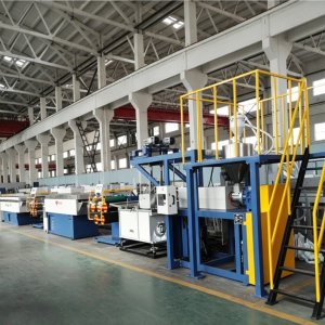
Monofilament production is a coupled system, typically:
Extrusion → Die → Quench → Drawing → Heat-setting → Winding
The key connection is this:
The die and quench set the strand’s starting geometry and temperature profile. Drawing then amplifies whatever non-uniformity you created upstream.
If the quench is uneven, you can create a filament with a skin/core temperature mismatch or ovality. When you draw that filament, the “weak” spots become break points.
That’s why the most reliable troubleshooting order is usually:
Confirm melt stability (extrusion)
Confirm quench symmetry (cooling)
Then tune draw ratio and draw-zone temperatures
Then tune winding tension and traverse
Extrusion vs drawing polymer: how to think about it
If you search for “extrusion vs drawing polymer,” the clean way to separate them is this:
Extrusion is a melt-flow shaping process. Your main variables are melt temperature/viscosity, pressure stability, filtration, and die conditions.
Drawing is a solid-state orientation process. Your main variables are draw ratio, traction, thermal window, and tension zoning.
Once you decide which physics you’re dealing with, troubleshooting gets much faster.
A practical troubleshooting rule: “Which stage can physically create this defect?”
Here are a few common symptoms and the stage that most often creates them.
If you see diameter drift over time
Look upstream first:
melt stability (feeding, temperature cycling, pressure trend)
quench temperature and water level stability
then check draw speed synchronization
Don’t start by “tightening the draw ratio.” If the input is drifting, the ratio just scales the drift.
If you see frequent breaks in the draw section
Look at:
quench stability (temperature, turbulence, path consistency)
draw-zone temperature uniformity
traction/slip on godets
then reduce or redistribute draw ratio (especially if you’re near the edge of the stable window)
If winding is unstable (telescoping, loose edges, hardness variation)
Treat winding as the last control loop:
check tension zoning (is winder tension feeding back into draw?)
check diameter stability upstream
check roller slip and speed ratio stability
Common misconceptions
“Drawing is just pulling the filament to the target diameter.”
Diameter reduction happens, but the main value is orientation. If you only chase diameter without controlling thermal window and traction, you’ll get unstable properties and breaks.
“If the filament is breaking, the extruder must be the problem.”
Sometimes, but not always. Breaks can be caused by upstream melt contamination or weak spots, but they’re very often caused by quench + draw-zone instability combined with an aggressive draw ratio.
“Once diameter is right, properties will follow.”
Diameter can look good while properties are unstable. Orientation and heat-setting control whether tensile, elongation, and shrinkage stay consistent spool-to-spool.
FAQ
Is drawing always required after extrusion for monofilament?
For most commercial monofilament applications, some form of drawing is used to reach the target balance of strength, stiffness, and elongation. The exact number of stages and ratios depend on polymer grade and end-use.
Does higher draw ratio always mean better strength?
Higher draw ratio generally increases orientation up to a point, but it also narrows your stable window. Beyond the material’s drawability (and your thermal window control), breaks and property scatter rise.
What equipment “does” the drawing process?
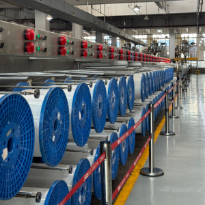
Typically a series of driven rollers (godets) with controlled surface speeds, often with heated zones (hot water tank/oven) and then a heat-setting span before winding.
Where should I measure to tell if the problem is extrusion or drawing?
Start with trends:
melt pressure trend and melt temperature behavior (extrusion)
quench temperature and path consistency (cooling)
speed ratio stability, slip indicators, and break location (drawing)
Next steps
If you’re trying to stabilize a line, the fastest way to isolate extrusion vs drawing issues is to map your current settings and symptoms by stage (resin, target diameter, quench temperature, draw ratios per stage, heating method, winding tension).
If you want a second set of eyes:
NLY can help you review your line configuration and define a practical startup/FAT checklist based on your polymer and target spec.
Start with the system overview in the NLY guide to how a plastic monofilament extrusion line works (it’s the same page linked earlier in this article).