If you’ve ever watched a monofilament or filament line in steady state, the impressive part isn’t that plastic flows out of a die.
The impressive part is that it keeps flowing as one continuous strand for hours—without diameter drift, ovality, breaks in drawing, or winding defects that force a stop.
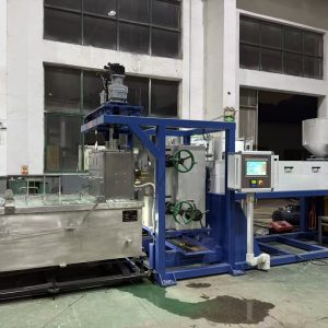
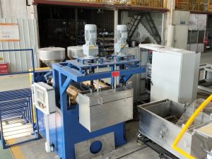
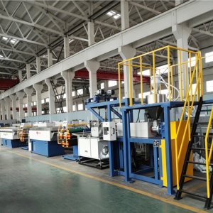
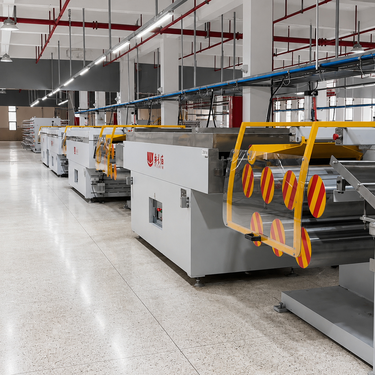
This article explains how a plastic filament extrusion line produces continuous “yarn,” and what each line section is really doing to keep the process stable.
First, clarify “yarn” vs filament vs monofilament
In plastics, people sometimes use “yarn” to mean continuous filament—a strand (or multiple strands) that’s produced continuously and wound onto packages.
To avoid confusion:
Filament: a continuous strand of plastic.
Monofilament: one solid strand designed to be used as a single filament (e.g., brush bristle, fishing line, zipper monofilament).
Multifilament textile yarn: many very fine filaments produced and combined into a yarn (common in textile spinning lines). That’s a different equipment family.
The line described below is the typical plastic filament/monofilament extrusion + drawing + winding system. If you want a deeper definition of terms and system scope, see NLY’s explainer on the monofilament extrusion process, and its overview of the continuous filament extrusion process.
The process chain in a continuous filament extrusion process (and what each section controls)
A stable plastic filament extrusion line is not one machine. It’s a synchronized system:
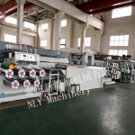
Material conditioning → extrusion/melt delivery → die → quench → drying → drawing → heat-setting → winding.
Below is what each stage controls—and why it matters.
1) Material conditioning: drying + stable feeding
What it is: resin handling (often including drying) plus a feeding system that keeps the extruder supplied consistently.
What it controls:
Moisture (critical for hygroscopic polymers like many nylons and PET)
Feed stability (avoids throughput swings that show up as diameter variation)
Why it matters for continuous filament: Moisture and inconsistent feed don’t just create cosmetic issues—they destabilize the melt and can cause bubbles/voids and weak spots that later break during drawing. Filament defect guides frequently flag moisture as a primary driver of bubbles.
2) Extruder + melt delivery: make the die see a stable melt
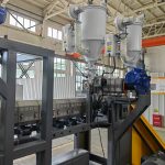
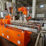
What it is: the screw extruder melts, mixes, and pressurizes the polymer so the die receives a uniform melt.
What it controls:
Melt temperature behavior (not just a setpoint)
Melt pressure trend (stable vs drifting vs oscillating)
Melt cleanliness (contamination, gels, degradation risk)
Why it matters: If melt delivery isn’t stable, downstream sections spend the whole shift “chasing” the instability with speed and tension changes—often creating more breaks.
A practical equipment-level map of a plastic monofilament extrusion line helps here: extrusion is the upstream “engine,” but line stability is a system outcome.
3) Die or spinneret: form the initial strand
What it is: tooling that shapes the molten polymer into a strand.
What it controls:
Initial strand geometry
Flow symmetry (which strongly affects roundness later)
Why it matters: Many buyers assume the die alone “sets the diameter.” In practice, the die establishes the starting point, but cooling symmetry and draw balance largely determine whether you hold diameter and roundness across shifts.
4) Quench cooling: lock in geometry before tension amplifies defects
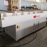
What it is: usually a water bath/tank that cools and solidifies the strand.
What it controls:
Cooling rate
Cooling symmetry around the strand circumference
Stability of strand path (centered, consistent entry angle/height)
Why it matters: If geometry isn’t “locked in” symmetrically, the next stages will amplify it into ovality and drift.
If you want a practical, plant-focused explanation of why this matters, NLY’s guide on the water bath cooling system breaks down cooling stability as a first troubleshooting priority.
Pro Tip: When quality shifts suddenly, stabilize cooling before you touch draw ratio. If the strand is already “frozen” asymmetrically, drawing just stretches the defect into something more visible.
5) Drying/aspiration: remove surface water for repeatable traction
What it is: removal of water after the quench section so rollers and heated zones behave consistently.
What it controls:
Water carryover into heated draw zones
Roller traction stability (slip risk)
Why it matters: If surface water changes friction unpredictably, you’ll see speed-ratio instability (real draw ratio differs from the “recipe”). That often looks like random breaks in drawing.
6) Drawing/orientation: set properties with draw ratio + temperature window
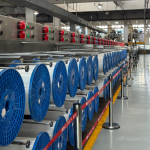
What it is: controlled stretching using godet rollers and heated zones.
What it controls:
Draw ratio (speed ratio between roller sets)
Orientation level (which drives strength/stiffness and elongation behavior)
Draw stability (traction, slip, tension hunting between zones)
Why it matters: This is where the strand becomes a usable filament. You’re aligning polymer chains to reach target mechanical behavior.
It’s also where continuity often fails: a slightly inconsistent upstream strand can survive cooling but snap when you push the draw window.
If you need a clear stage definition for teams who mix terms, NLY’s explainer on the difference between extrusion and drawing is a good shared reference.
7) Heat-setting/annealing: make the filament stop “changing its mind”
What it is: a controlled heat exposure (often under controlled tension) to reduce internal stress.
What it controls:
Shrinkage behavior
Dimensional stability over time
Why it matters: Without stable stress control, you can hit diameter at the winder and still see problems later: curl, unpredictable shrinkage, or package deformation.
8) Winding: tension and package build (the last stability loop)
What it is: winding onto spools/bobbins with controlled traverse and tension.
What it controls:
Winder tension control (tension zoning)
Traverse pattern and package hardness
Why it matters: Winding is not “just collecting.” Poor tension control can feed back upstream as extra draw, which changes diameter and triggers breaks.
This is why experienced teams treat winding as the last loop to tune—after melt, quench, and draw are stable.
The five stability loops that keep filament continuous
If you want one mental model to teach new engineers and operators, use this:
A continuous filament line stays continuous because it keeps five linked loops stable:
Melt delivery stability (pressure + temperature trends)
Geometry lock-in (die + quench symmetry)
Orientation stability (draw ratio + temperature window + traction)
Stress control (heat-setting/annealing)
Tension + package control (winding)
This “linked loops” view is outlined in NLY’s continuous filament extrusion process overview, and it’s a practical way to troubleshoot without guessing.
Where continuity breaks: common defects and first checks
Below are common symptoms and the fastest upstream checks to run.
Diameter drift or variation
What you see: diameter slowly drifts or oscillates.
Most likely drivers:
unstable melt pressure / temperature behavior
feeding inconsistency
haul-off speed instability
Ovality (out-of-round)
What you see: diameter measures “OK” in one direction but fails roundness.
Most likely drivers:
quench instability or asymmetry
die-to-bath alignment issues
tension disturbances during early solidification
Start with cooling. NLY’s water bath cooling system guide is written specifically around this reality.
Bubbles/voids
What you see: bubbles, voids, porosity, weak spots.
Most likely drivers:
moisture in resin
thermal degradation from overheating or long residence time
3DEVO’s guide on common filament defects is a straightforward reference for why drying discipline matters.
Surface lines, roughness, “sharkskin,” streaks
What you see: visible lines, roughness, surface defects.
Most likely drivers:
contamination / gels
die condition (scratches, deposits)
shear-related issues (melt fracture)
Chem-Trend’s overview of common extrusion defects is a helpful general reference for these surface-quality categories.
Breaks during drawing
What you see: filament snaps in the draw zone.
Most likely drivers:
draw ratio too aggressive for the current strand quality
incorrect draw temperature window
traction/slip issues on godets
upstream weak spots (moisture, contamination)
When this happens, the best troubleshooting order is usually: melt stability → quench stability → draw stability → winding (see NLY’s extrusion vs drawing explainer for the logic).
What to monitor on a stable line (a practical checklist)
If you want continuity, you need more than setpoints—you need trend discipline.
Here’s a practical list to track per shift:
Melt pressure trend near the head: stable vs rising vs oscillating
Melt temperature behavior: stable across zones, no cycling
Quench water temperature and level stability (and obvious turbulence)
Actual speed ratios across godets (your true draw ratio)
Tension stability between zones (watch for “hunting”)
Diameter + ovality measurement method
FAQs
Is the die size the main controller of final filament diameter?
It sets the starting point, but in many real lines the final diameter and roundness depend heavily on quench symmetry and draw balance. If cooling is unstable or draw ratio is “hunting,” you’ll see diameter issues even with a good die.
Why does a line that runs fine at low speed start breaking when you speed up?
Because you’ve changed the stress and traction window across multiple zones at once. Speed changes often reveal hidden instability—melt delivery fluctuations, quench limitations, godet slip, or winding tension feedback.
Where should troubleshooting start: winder, draw, cooling, or extruder?
Start upstream. The fastest, lowest-cost isolation path is usually:
melt stability, 2) quench stability, 3) draw stability, 4) winding.
Next steps
If you’re planning a new line—or trying to stabilize an existing one—NLY can help you define a practical process window and configuration.
Send these 4 inputs:
polymer(s) (PA/PET/PP/PE; virgin vs recycled),
target diameter range + tolerance and any ovality limit,
target output (kg/h) and line speed,
your top scrap driver (ovality, bubbles, surface lines, breaks).
Then we can recommend a line layout and controls approach, and align on a trial/FAT plan before production.