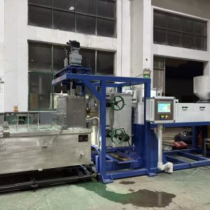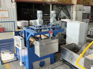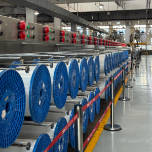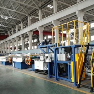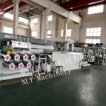
If you’ve ever watched a monofilament line run well, it looks deceptively simple: pellets in, filament out, spools stacked at the end.
In reality, you’re running a coupled system where one stage’s drift becomes the next stage’s scrap. A useful mental model is the one outlined in NLY’s overview of the continuous filament extrusion process (2026):
melt delivery → shaping/cooling → drawing/orientation → heat-setting → winding
This article walks through that chain in plant terms—what happens, what each step controls, and where common defects usually originate.
First: “Filament” vs “Monofilament” (and why the process looks like this)
Monofilament means one solid strand (not a yarn made from many fine filaments). In production terms, the goal isn’t just “make a strand.” It’s to keep three things stable:
Geometry: diameter and roundness/ovality
Properties: strength, elongation, stiffness, shrinkage behavior
Stability: breaks, scrap rate, and consistent winding
The reason the line has so many stages is simple: no single stage can control all three.
The monofilament extrusion process: from pellets to spools
A practical monofilament line flows like this:
resin handling and drying (when required)
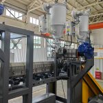
extrusion + melt filtration + stable melt delivery to the die
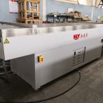
die/spinneret + quench water bath
take-off/godets
drawing (one or multiple stages)
annealing/heat-setting
diameter monitoring (optional) + winding
The sections below break down what each zone controls and how to troubleshoot it.
Step 1: Resin handling, drying, and stable feeding
If you only remember one thing: your melt can’t be stable if your resin condition isn’t stable.
What this step controls
Moisture-driven defects (bubbles/voids, splay, unstable flow)
Viscosity stability across the shift (and therefore pressure and diameter stability)
What to watch
Moisture sensitivity: nylon/PA and PET are classic problem materials if drying discipline slips.
Feeding consistency: bridging, segregation, or fluctuating feed rate will show up downstream as pressure and diameter swings.
⚠️ Warning: When you see bubbles/voids, don’t start by “turning up temperature.” Start by confirming drying and feeding discipline first.
Step 2: Extrusion and melt delivery (make the die see a stable melt)
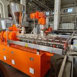
Extrusion is often described as “melting plastic,” but that’s incomplete. In a monofilament line, the extruder section is doing multiple jobs at once: feed, melt, homogenize, build pressure, and meter flow.
NLY summarizes this clearly when explaining what plastic extrusion is (2026): resin enters through the hopper, is conveyed and melted by the screw/barrel, stabilized/filtered before the die, then shaped and cooled downstream.
What this step controls
Melt temperature uniformity (avoids cold streaks and viscosity scatter)
Melt pressure stability (avoid surging that turns into diameter variation)
Contamination control (gels/specks, die lines, premature screen loading)
What to watch
Pressure trend (steady vs rising vs oscillating). An oscillating pressure trend is usually telling you “something upstream is not stable.”
Temperature cycling (heater control hunting) that causes viscosity swings.
Filtration behavior: if screen packs load and unload, you can get a “sawtooth” pressure pattern that prints itself into the filament.
Step 3: Filtration, screen pack, and “clean melt” discipline
Filament is unforgiving: a small contaminant that would disappear in a thicker product can cause a nick, a weak spot, or a surface line.
What this step controls
Defects caused by contamination (gels, black specks, die lines)
Melt uniformity (back pressure can improve homogenization, but restrictions can also create instability)
What to watch
Rising head pressure that correlates with screen loading
Black specks or lines that repeat consistently (often tooling or contamination related)
Step 4: Die/spinneret + quench water bath (lock in geometry)
The die forms the initial strand. The quench makes that geometry “real.”
This is why NLY emphasizes the die + quench section in its monofilament extrusion process step-by-step (2026): if the strand isn’t cooled symmetrically and consistently, you can bake in ovality and create tension swings that show up later as breaks or unstable winding.
What this step controls
Starting diameter and surface condition
Roundness/ovality risk (often created here, amplified later)
Downstream stability (a bad quench creates a filament that’s hard to draw consistently)
What to watch
Quench symmetry: water flow pattern, turbulence, and consistent strand path.
Alignment: die exit → bath entry height/angle and guide condition.
Pro Tip: If you’re chasing ovality, treat the quench like a precision process—not “just a water tank.” Confirm flow pattern and path stability before you change draw ratios.
Step 5: Take-off/godets and tension zoning
The take-off/godets are not only moving the filament forward—they’re establishing the line’s tension handoffs.
What this step controls
Surface damage from slip/rubbing
Tension stability between zones (prevents “tension hunting”)
What to watch
Traction consistency (wrap, roller surface condition)
Micro-slip during ramps/acceleration
Step 6: Drawing (orientation) — where properties and final diameter are really set
Drawing is where you intentionally stretch the quenched strand using speed ratios between rollers.
If you want a clean conceptual separation, NLY’s explanation of the difference between extrusion and drawing (2026) is the simplest framing:
Extrusion is a melt-flow shaping process (controls melt quality and initial geometry).
Drawing is a solid-state orientation process (controls molecular orientation and therefore final properties).
What this step controls
Final diameter (within a stable window)
Mechanical behavior (strength, stiffness, elongation)
Break frequency and stability during speed changes
What to watch
Draw ratio as a recipe: stage speeds, tension window, and draw-zone temperature window.
Thermal window: too cold → breaks and surface damage; too hot → loss of orientation stability.
For a deeper view of the draw section mechanics and failure modes, see NLY’s monofilament drawing machine explainer (2026).
Step 7: Heat-setting/annealing — controlling shrinkage and dimensional stability
After drawing, the filament contains internal stress. Heat-setting under controlled tension stabilizes it so it doesn’t “change its mind” later (shrink unpredictably, curl, or drift in properties).
What this step controls
Shrinkage behavior
Dimensional stability and repeatability
Curl/coil memory issues
What to watch
Temperature stability and residence time
Consistent tension through the heat-setting zone
Step 8: Winding — package build is part of quality, not just packaging
Winding is where stable tension becomes a package that can unwind cleanly without damage.
A key point from NLY’s continuous filament extrusion process overview is worth repeating: when winding is unstable, the root cause is often upstream (melt delivery drift, quench instability, draw-zone issues), not the winder itself.
What this step controls
Package build quality (hardness, edges, telescoping)
Downstream usability (unwinding stability, surface damage risk)
What to watch
Tension stability (avoid spikes and hunting)
Traverse consistency
Early package checks (start/mid/full): edges, hardness, telescoping
A practical defect-to-stage map (where to start troubleshooting)
When the line gets unstable, don’t chase symptoms at the end. Start where the defect can physically be created.
Bubbles, voids, splay
Start at drying + feeding, then confirm melt stability.
Moisture and volatiles are common root causes. A general extrusion troubleshooting breakdown like JF Extruder’s extrusion troubleshooting guide (2026) puts moisture problems and feeding stability at the top for a reason.
Diameter drift or cycling
Start at melt delivery stability, then quench stability, then speed synchronization.
Pressure trend and feeding consistency first.
Quench bath temperature/level stability and path consistency next.
Ovality (out-of-round)
Start at die-to-quench alignment and quench symmetry.
Uneven cooling and inconsistent strand path can lock in asymmetry early.
Die lines or repeating surface marks
Start at tooling condition and contamination control.
Die land damage or contamination at the die exit is a common cause.
Melt fracture / rough surface
Start at melt temperature/shear and die restriction.
Often tied to high shear rate, low melt temperature, or die lip restriction.
Where NLY fits (without turning this into a sales pitch)
If you’re building or upgrading a filament/monofilament extrusion line, the hard part isn’t listing the equipment—it’s defining a control plan that keeps melt delivery, quench symmetry, draw ratio/thermal window, and winding tension stable together.
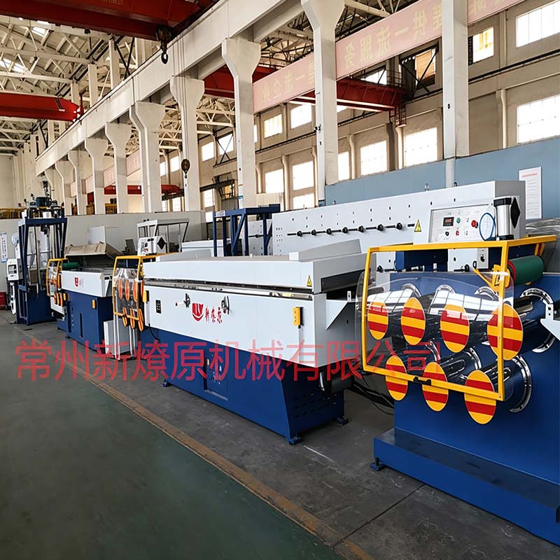
Changzhou New Liaoyuan Machinery (NLY) builds monofilament extrusion systems with that end-to-end process view (melt delivery → shaping/cooling → drawing → heat-setting → winding).
Next step: de-risk your line setup
If you want a second set of eyes on your process chain, share:
polymer (PP/PE/PET/PA and whether you run regrind/recycled content)
target diameter range + tolerance/ovality limit
where instability shows up first (pressure trend, diameter drift, draw breaks, or winding defects)
Then we can map a line configuration and a practical run-acceptance plan (including a sample/FAT checklist) before you commit.