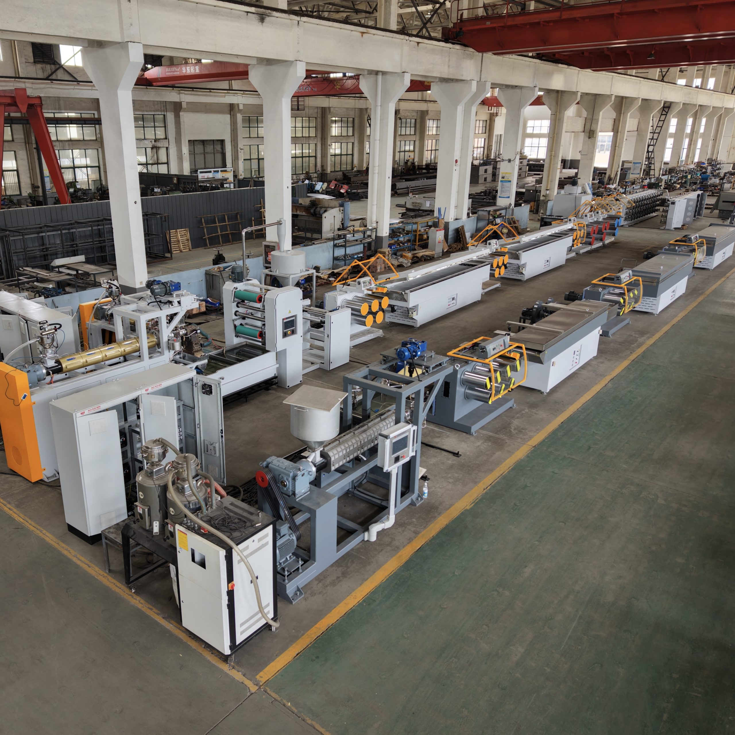
If you’ve ever increased line speed to hit an output target and immediately saw diameter drift, ovality, surface marks, breaks, or unstable winding, you’ve already learned the hard truth:
An extrusion line doesn’t have “one speed.” It has several speeds that must stay in relationship—because the process is a coupled system.
In practical terms:
What happens in melt delivery shows up as dimensional variation.
What happens in cooling gets amplified in drawing.
What happens in tension control shows up as package defects (and sometimes feeds back upstream).
Before the details, here’s the simplest mental model: speed control extrusion line performance is mostly about keeping the right ratios stable—output vs take-off, draw-stage speed ratios, and winding tension—so small disturbances don’t turn into scrap.
This explainer breaks down what speed control actually changes, why problems appear when you change speed, and what to monitor so your adjustments are repeatable across shifts.
Speed control extrusion line performance: why it changes line output
On practical lines, “speed control” usually means coordinating at least four speeds. Most “speed problems” are really ratio problems.
1) Extruder screw RPM (extruder screw speed control)
The screw is the engine that melts and pressurizes polymer. Changing screw RPM changes:
melt throughput (kg/h)
melt pressure behavior
shear and mixing intensity
residence time (how long material stays in the barrel)
On paper, raising RPM increases output. On the floor, raising RPM can also make instability more visible if feeding, temperature control, or filtration isn’t stable. Dynisco notes that closed-loop die pressure control can reduce pressure fluctuations by trimming screw speed to hold a pressure setpoint (see Dynisco’s “Closed Loop Pressure Control for the Extrusion Process”).
2) Haul-off / take-off speed (haul-off speed and diameter control)
The haul-off (take-off) is where many plants accidentally “control diameter” without calling it that.
As NLY explains in “What Is Plastic Extrusion?”, the haul-off pulls product at a controlled line speed, and that speed directly affects dimensions.
If the haul-off pulls faster without a matched increase in stable extruder output, the strand gets stretched more. That changes how much material ends up in each meter of product.
3) Draw roller surface speeds (draw ratio control monofilament)
In monofilament production, drawing is where speed becomes properties.
Drawing is controlled by roller surface-speed ratios. NLY explains this directly in “How Multi-Stage Draw Ratio Control Keeps Stretching Stable”: a stage draw ratio is approximately a speed ratio (for example, V2/V1).
Higher draw ratios can increase orientation (which can affect stiffness/strength), but they also tighten the stability window. If cooling or heating is inconsistent, that window gets even smaller.
4) Winder speed and tension (winding tension control)
Winding is not just “collecting the product.” It is a control loop with its own physics.
If winding tension swings, it can:
create soft packages, telescoping, or edge build issues
change the effective tension upstream
disturb draw stability in sensitive products
NLY’s overview of the downstream chain emphasizes troubleshooting order—stabilize upstream first, then tune winding (see “Cooling, stretching and winding process in filament production line”).
Why speed changes create diameter variation
There are two common reasons diameter “moves” after a speed change.
Output and take-off must match (synchronization)
Think of the line like this:
The extruder delivers a certain mass per time.
The haul-off removes a certain length per time.
If you change one side without the other, mass per length changes—and diameter changes.
A clear explanation of this relationship is described in the JF Extruder article on extruder output and haul-off speed synchronization. Their diagnostic framing is useful: if dimensions drift, ask whether output is stable or whether the drift is downstream.
The extruder doesn’t respond instantly
When you change screw RPM, you also change shear heating and residence time, which can change melt temperature and viscosity. That means the system needs time to reach a new steady state.
If you keep “correcting” every 30 seconds, you can create oscillation—especially if cooling valves or temperature controllers are already cycling.
Key Takeaway: Diameter stability is mainly a ratio outcome, not a single setpoint.
Why speed changes create surface defects and instability
Even if you can hold diameter, you may still lose surface quality at higher speeds.
Higher speed can increase shear at the die
As throughput rises, shear stress at the die wall can rise. One visible symptom is a rough surface defect often described as sharkskin or melt fracture.
A practical troubleshooting overview is provided in BYU-Idaho’s open text “Extrusion Problems and Troubleshooting”, which notes that reducing speed (and/or adjusting temperature and die conditions) is a common lever when flow instabilities appear.
Faster line speed increases cooling demand
Cooling isn’t just “make it cold.” It’s “make it repeatable and symmetric.”
If the strand is still too soft when it meets any guide, roller, or traction device, you can get deformation and marks. If cooling is uneven, you can get ovality.
NLY’s filament line overview stresses checking cooling stability and path consistency before chasing draw settings (see “Cooling, stretching and winding process in filament production line”).
Why speed changes affect mechanical properties
For monofilament, properties are heavily influenced by how much the filament is stretched and heat-conditioned downstream.
The key point for operators and managers is simple:
Die size is not final size.
Extrusion speed is not the same as draw speed.
Draw ratio is where the material structure changes.
When you increase overall line speed, you often end up changing one or more of these:
draw ratio (speed ratio between stages)
draw-zone temperature window (how much time the material has to respond)
heat-setting/annealing residence time
If your line is near the edge of the stable window, small changes can flip behavior from “stable” to “break-prone.” That’s why multi-stage drawing exists: it can widen the usable window by splitting the total stretch into manageable spans.
How coordinated speed control works in real plants
Most stable lines rely on coordinated control architecture, not operator memory.
Master/follower speed coordination
In many lines, a PLC sets one master reference and downstream stations run as a ratio of that master.
Plastics Technology describes how multiple loops can run in parallel—one loop synchronizes speed between extruder and puller, while other loops trim based on measurement (see “What Makes for ‘Perfect’ Control in Tubing Extrusion?”). Even though that article focuses on tubing, the control concept—synchronization + trim loops—maps well to monofilament lines too.
Pressure feedback on screw speed
Some systems use pressure feedback to automatically adjust screw speed. For example, NLY lists an “RKC pressure automatic feedback system” on its Monofilament Extrusion Line product page.
The practical point: pressure trend is often a better early signal than “the diameter you see five minutes later.”
A practical checklist when you ramp line speed
The goal isn’t “maximum speed.” It’s stable production speed you can repeat across shifts.
When you change speed, monitor trends (not single readings):
Head/melt pressure trend
steady vs rising (restriction loading) vs oscillating (instability)
NLY highlights trend-watching in its extruder working principle explainer.
Motor load (amps/torque) trend
drifting upward can indicate restriction or abnormal load
Diameter + ovality trend
don’t rely on one-axis checks when ovality matters
Quench stability
water temperature stability, level stability, and flow symmetry
Draw stability
verify actual speed ratios, not only recipe values
watch for slip/traction changes at godets
Tension stability
look for tension “hunting” (oscillation) between zones
Package build
check edges early (start, mid, near full package): hardness, telescoping, loose edges
If you’re trying to increase output without losing stability, NLY’s process checklist approach in “How to increase monofilament extrusion line output without losing stability” is a solid related read.
⚠️ Warning: If your winder becomes unstable right after a speed increase, treat it as a symptom until you’ve confirmed cooling and draw stability. Winding often amplifies upstream variation.
Common misconceptions about speed control
“If diameter drifts, just change haul-off speed.”
Small trim adjustments can help, but if melt delivery or cooling is drifting, haul-off changes often just scale the problem. Start with pressure trend and quench stability.
“The recipe says the draw ratio is correct, so drawing is fine.”
Draw ratio is a real speed ratio between real rollers. Slip, wear, or unstable drive control can change the actual ratio even when the HMI value looks fine.
“Winding is downstream, so it can’t affect upstream quality.”
On sensitive products, tension disturbances can propagate upstream. That’s why tension zoning matters.
Next steps
If you want to make speed changes more repeatable, start by documenting three things for your current product:
polymer (PP/PE/PET/PA and whether it includes regrind),
target diameter range and tolerance/ovality limit,
where the instability shows up first (pressure trend, diameter drift, draw breaks, or winding).
From there, you can map which speed ratio is the “true controller” for your issue and lock in a stable production window.