.jpg)
In synthetic fiber and industrial monofilament manufacturing, dimensional stability is the foundational benchmark of quality. Whether producing high-tenacity nylon lines for fishing nets, PET monofilaments for zipper teeth, PP bristle fibers, or industrial mesh yarns, maintaining a tight filament diameter tolerance—often within ±0.005 mm to ±0.01 mm—determines product performance, tensile strength, and downstream processability.
When filament diameter fluctuates during extrusion, line operators frequently struggle to identify the exact cause. Diameter instability is rarely the result of a single faulty setting. Instead, it is the downstream symptom of a coupled thermal, mechanical, and rheological system. A slight change in melt temperature alters viscosity, which shifts die backpressure, fluctuates output mass flow, and ultimately changes the physical dimensions of the extruded strand.
Understanding why filament diameter changes during extrusion requires analyzing the process across three core domains: polymer melt physics, upstream plasticizing stability, and downstream take-up dynamics.
The Core Physics: Mass Conservation & Polymer Viscoelasticity
To diagnose diameter variations systematically, engineers start with the fundamental mass conservation law governing continuous extrusion.
At steady-state operation, the volumetric output exiting the spinneret die must equal the volumetric take-up rate of the downstream haul-off or godet rollers:
Volumetric Flow Rate = Melt Density × Die Orifice Area × Extrusion Velocity = Final Filament Cross-Sectional Area × Take-Up Velocity
From this relationship, final filament diameter (D) is controlled by three primary variables:
Mass Flow Rate (m): The mass of molten polymer delivered through the die per second.
Polymer Melt Density (ρ): The density of the molten resin, which changes with melt temperature and pressure.
Linear Take-Up Velocity (v): The surface speed of the haul-off puller or first godet roller.
If mass flow rate or melt density drifts while take-up velocity remains constant, filament diameter changes immediately. Conversely, if haul-off speed fluctuates while melt delivery remains steady, the strand is stretched unevenly along its length.
Polymer Viscoelastic Memory and Die Swell (Barus Effect)
Polymer melts are not simple Newtonian fluids; they possess viscoelastic memory. As long-chain polymer molecules pass through the restricted channels of an extruder screw and spinneret die, they are forced into alignment under high shear stress. Upon exiting the die orifice into atmospheric air or a quenching bath, those shear stresses abruptly release.
The constrained polymer chains relax and recoil back toward their random coil configurations. This physical relaxation causes the extruded strand to contract in length and expand in cross-sectional area—a phenomenon known in polymer rheology as die swell or the Barus effect.
According to research published in the NCBI Polymer Rheology Series (2022), die swell ratio (B = D swell / D die) increases significantly when:
Melt Temperature Drops: Lower melt temperature increases polymer elasticity, leading to higher die swell ratio.
Shear Rate Rises: Higher screw speeds force polymer chains through the die faster, increasing elastic energy storage and swell.
Die Land Length is Short: Short die land length gives polymer chains insufficient time to relax shear stress before exiting the orifice.
When barrel or die temperatures drift across shifts, die swell fluctuates unpredictably, causing diameter changes even if the volumetric screw output remains nominally constant.
Shear Stress Limits and Melt Fracture (Sharkskin)
If shear stress at the die wall exceeds a critical threshold for a given polymer melt, the extrudate loses smooth surface flow. The outer layer of the strand undergoes periodic stick-slip failure at the die exit, causing fine surface waviness or rough diameter ripples known as melt fracture or sharkskin. Controlling die wall temperatures and optimizing die entrance angles are essential to prevent shear-induced surface roughness from ruining diameter uniformity.
Upstream Causes: Extruder Feeding & Thermal Instability
Upstream instability in the extruder section is the most common origin of periodic diameter fluctuations. When evaluating the primary plastic monofilament extruder working principle, consistent solid bed conveying in the feed zone directly dictates pressure stability at the die.
Upstream Root Cause | Physical Mechanism | Impact on Filament Diameter | Primary Solution |
|---|---|---|---|
Feed Hopper Bridging / Rat-Holing | Intermittent solids feeding into screw flights causes periodic starvation in the feed zone. | Low-frequency periodic surging (1–5 minute cycles) with thick and thin sections. | Install vibrating hopper agitators, smooth hopper walls, and maintain steady regrind ratio. |
Barrel Temperature Drift | Unstable PID heater band cycling causes temperature swings across barrel zones. | Melt viscosity drifts; cooler melt increases backpressure and reduces die flow. | Calibrate thermocouples, tighten PID parameters to ±1°C, and inspect solid-state relays. |
Screw Rotation Pressure Surge | Flight geometry pushes discrete melt pulses with every screw revolution. | High-frequency pressure pulsation synchronized with screw RPM. | Use barrier screw designs with mixing elements, or install a melt gear pump. |
Moisture Volatilization | Moisture in hygroscopic resins (Nylon PA6/66, PET) vaporizes into steam bubbles inside the barrel. | Internal micro-voids, bubbles, and sudden localized diameter spikes or dips. | Dehumidify virgin resin and regrind to recommended moisture levels (< 0.02% for PET/PA). |
Key Takeaway: Low-frequency diameter variations (cycling every 1 to 5 minutes) usually point to feed hopper bridging or barrel temperature cycling. High-frequency variations (cycling every few seconds) typically indicate screw rotation surging or motor speed instability.
Melt Metering & Die Pressure Stabilization
While a single-screw extruder is effective at melting and homogenizing raw plastic resin, it is inherently an imperfect pressure pump. Changes in screw backpressure, screen pack contamination, or feed bulk density directly affect volumetric output at the die.
Without pressure buffering, pressure fluctuations at the die inlet can reach ±10% to ±15%. Because throughput scales non-linearly with die backpressure, a 10% pressure surge creates unacceptable diameter spikes downstream.
Item | Detail |
|---|---|
Unbuffered Flow | Extruder Screw → Screen Pack → Spinneret Die (Pressure Fluctuation: ±10–15%) |
Buffered Flow | Extruder Screw → Screen Pack → Gear Melt Pump → Spinneret Die (Pressure Fluctuation: < ±1%) |
The Role of Precision Gear Melt Pumps
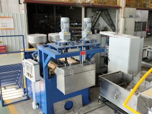
To achieve tight tolerances, modern industrial production lines install a positive-displacement gear melt pump between the screen changer and the spinneret die.
According to technical specifications published by PSI Polymer Systems (2025), integrating a precision melt gear pump decouples extruder screw pressure surging from the die inlet. The intermeshing counter-rotating gears deliver a constant volumetric displacement (cc/rev) to the die regardless of upstream pressure swings.
Key performance advantages of gear pump integration include:
Die Pressure Swing Reduction: Reduces pressure fluctuations at the die inlet from ±10–15% down to less than ±1%.
Output Linearization: Volumetric flow rate becomes strictly proportional to pump gear RPM, eliminating output drifting caused by screen pack loading.
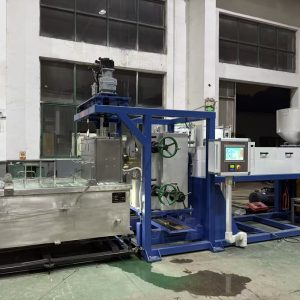
Narrower Tolerance Bands: Enables high-precision manufacturers like Changzhou New Liaoyuan Machinery Co., Ltd. (NLY) to maintain monofilament diameter variations within ±0.005 mm across high-speed continuous production runs.
Screen Pack Loading Effects
As continuous extrusion progresses, foreign contaminants and degraded gels accumulate on the filter screen pack. As filtration resistance increases, head pressure behind the screen pack rises. If the system relies solely on screw speed without gear pump metering, throughput slowly declines over hours, causing gradual diameter shrinkage downstream.
Downstream Causes: Quenching, Drawing & Winding Dynamics
Even when the extruder and melt pump deliver a perfectly uniform volume of molten polymer through the spinneret, filament diameter can still degrade during downstream conditioning.
Quench Water Bath Instability and Ovality
As molten polymer strands leave the die, they pass through a brief air gap before plunging into a water quench bath for solidification. Process fluctuations in this zone create two distinct defect types: overall diameter drift and ovality (out-of-round cross-sections).
Die-to-Water Air Gap Variance: If the distance between the die face and the water surface fluctuates due to water level waves, the strand experiences varying degrees of air drawdown before cooling, altering initial strand diameter.
Water Bath Turbulence: High-velocity water inlet streams or turbulent currents push against the semi-molten strands, causing transverse vibration and asymmetric cooling, which leads to oval filament profiles.
Quench Temperature Fluctuations: Water bath temperature controls the crystallization rate of materials like PET and HDPE. Unstable water temperature shifts the point of solidification along the strand path, altering total thermal shrinkage.
Godet Roller Speed Synchronization and Mechanical Slip
After quenching, monofilaments pass through primary godet roller units, hot water orientation tanks, and secondary drawing godets to align molecular chains and build tensile strength.
The relationship between roller speeds defines the draw ratio (DR = v godet2 / v godet1). Understanding speed control across the extrusion line is critical because any speed mismatch between drive motors translates directly into diameter variations:
Roller Surface Slip: If the filament wraps around godet rollers without adequate traction or nip roll clamping, the strand slips periodically, causing sudden localized diameter thickening.
Drive Motor Hunting: Analog VFD drive drift or speed controller hunting creates small speed oscillations between godet sets, stretching the strand unevenly during molecular orientation.
Pro Tip: Always verify actual godet surface speeds with a calibrated digital tachometer. Displayed motor RPM on digital operator panels can hide mechanical drive belt slip or gear wear.
Winder Tension Hunting
The final stage of the monofilament production process is spool winding. If winder tension is set too high or if dancer arm tension control hunts, the winder exerts excess mechanical pull on warm, un-annealed monofilament coming off the final godet, stretching the strand on the spool and causing under-gauge diameter defects.
Diagnostic Checklist: Periodic vs. Random Diameter Fluctuations
When troubleshooting diameter variations on an operational extrusion line, observing the frequency pattern of the defect quickly narrows down the root cause.
Symptom Pattern | Observable Frequency | Most Likely Root Cause Zone | Recommended Diagnostic Action |
|---|---|---|---|
Periodic Long Cycles | Fluctuation every 1 to 5 minutes | Extruder Feed / Hopper | Inspect hopper bridging, regrind ratio consistency, or barrel PID temperature cycling. |
Periodic Short Cycles | Fluctuation every few seconds | Screw Rotation / Motor Drive | Check screw RPM stability, drive motor belt slip, or install a melt gear pump. |
High-Frequency Ripples | Continuous micro-variation along strand | Die Swell / Melt Fracture | Check melt temperature profile, increase die zone heat, or inspect die land surface finish. |
Sudden Localized Dips | Random short thin sections | Water Bath / Godet Slip | Check water quench level turbulence, air gap consistency, and godet roll traction. |
Spikes and Bubbles | Irregular localized bulges | Material Moisture | Test resin moisture levels; verify dehumidifying dryer dew point (< -40°C). |
Gradual Shift Over Shift | Diameter shrinking over 4 to 8 hours | Screen Pack Loading | Monitor pre-filter melt pressure; perform screen changer cleanout or filter replacement. |
Engineering Solutions for Tight Diameter Control
To eliminate diameter variations and achieve stable high-speed output, leading monofilament machinery builders implement integrated multi-layer control architectures.
Process Control Loop:
Dual-Axis Laser Gauge (Real-Time Diameter Signal) → PLC Controller
Gear Melt Pump RPM Control Godet Puller Speed Trim
1. Dual-Axis Laser Optical Diameter Gauges
Positioned immediately after the quench bath or final drawing godet, non-contact dual-axis (X/Y) laser calipers continuously measure strand diameter at high frequencies (up to 1,000 Hz). Measuring along two orthogonal axes ensures early detection of both average diameter drift and ovality.
2. Closed-Loop Feedback Control (PID Trim)
Digital laser gauge outputs feed real-time signals back to the main extrusion PLC. If the average strand diameter trends above nominal target, the control system automatically applies a precise micro-trim speed adjustment to the haul-off godet or adjusts gear pump RPM, holding diameter within ultra-tight limits.
3. Integrated Line Control Systems
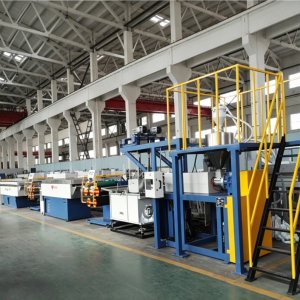
Maintaining consistent output requires looking at key factors affecting monofilament quality as a unified process. Standardizing on precision machinery equipped with synchronized AC servo drives, multi-zone barrel cooling, precision gear pumps, and stable water quench management eliminates process variables before they cause defects.
Frequently Asked Questions (FAQ)
How does die swell affect final filament diameter after drawing?
Die swell increases initial strand diameter immediately at the die exit before drawing. However, if die swell fluctuates due to temperature variations, the starting cross-sectional area entering the draw zone shifts. Because the draw ratio remains fixed by godet speeds, a fluctuating initial strand diameter results in a fluctuating final drawn diameter.
Why does filament develop ovality instead of remaining round?
Ovality occurs when cooling or mechanical force is asymmetric. Primary causes include turbulent water flow in the quench tank, uneven die orifice wear, die land thermal gradients, or excessive guide wire contact pressure while the strand is still semi-molten.
What is the single most effective hardware upgrade to stop diameter surging?
Installing a positive-displacement gear melt pump between the extruder and die is the single most effective hardware upgrade. A melt pump absorbs upstream extruder pressure surges and delivers a pulsation-free volumetric flow rate to the die, reducing die pressure fluctuations to less than ±1%.
Summary & Next Steps
Filament diameter changes during extrusion when melt delivery mass flow, polymer melt density, or downstream take-up speeds drift out of balance. By systematic evaluation of polymer die swell physics, feed hopper stability, gear pump pressure buffering, water quench conditions, and godet speed synchronization, line operators can isolate root causes and re-establish tight dimensional tolerances.
For synthetic fiber and monofilament manufacturers seeking consistent, high-yield production, engineering precision into every zone of the extrusion line is essential. To explore technical line configurations, advanced melt pump integration, and high-precision monofilament machinery solutions, consult the engineering team at Changzhou New Liaoyuan Machinery Co., Ltd. (NLY).